The PanelOne LCD display and control panel was originally designed for RAMPS1.4, and that is still the most sensible way to use it as it uses two 2x5 IDC cables that are readily available. The PanelOne circuit board is designed to work with 3.3V and 5V electronics and this weekend I tested it with Sanguinololu (effectively going full circle back to the original Panelolu - just a lot easier to put together and use!)
This works fine, although you do need to be careful to plug the pins in correctly:
The correct pins for Sanguinololu are:
Wire number PanelOne Sanguinololu
Aux2
1 5V 5V
2 GND GND
3 EN B Rx1
4 EN A Tx1
5 LCD DB7 A4
6 LCD RS PWM
7 LCD DB6 A3
8 LCD E SDA
9 LCD DB5 A2
10 LCD DB4 A1
Aux3
1 Not Connected
2 Not Connected
3 CS A0
4 CLK SCK
5 DO MOSI
6 DI MISO
7 EN SW SCL
8 VCC 5V
9 Not Connected
10 Not Connected
This blog post has a good image of the location of each pin on the Sanguinololu, re-posted below:
The IDC cables are numbered with wire 1 being the red coloured wire.
This will work out the box with the T3P3 version of Marlin by enabling #SDSUPPORT and #ULTIMAKERCONTROLLER in configuration.h
The process followed can be adapted to use the PanelOne on any electronics that runs Marlin and has enough free pins. Do let me know if you get it working on another board!
This is the archive blog for Think3dPrint3d, please see Duet3d.com for up-to-date information
Showing posts with label PanelOne. Show all posts
Monday, 20 October 2014
Friday, 22 August 2014
Arduino based IDC cable tester
We use IDC terminated ribbon cables for the PanelOne LCD controller that we use in our Mini Kossel 3D Printer kits. Its a slow process to test these cables by confirming that the LCD, SD card, encoder etc all work so I looked for an IDC ribbon cable tester. I found a few online but they ran to ridiculous prices (~£250+) so decided to make one using an Arduino Mega and some strip board:
The circuit schematic includes the connections for a PanelOne as I had a prototype board that was no longer being used, however any 20x4 LCD screen and push switch would work.
It uses the internal pullup resistors on the arduino pins so no external components are required other than the connecting wires and headers.
I wrote a simple Arduino sketch to check the cable and display the results. It finds open and crossed wires:
The next step will be to make a circuit tester for the 50 way Duet-Duex4 expansion header cables however that would require 100 pins which is more than is available on the Mega.... I2C port expanders here we come! Also I think a PCB will be required as 100 wires on stripboard would take far too long.
As usual its all open hardware and software - available on the Think3dPrint3d Github.
I hope someone finds this useful and I would be interested to see if anyone else tries this!
As can be seen there has been no time wasted on making it look pretty, in fact it is probably the ugliest circuit I have made, ever, however it works and tests cables!
![]() |
| Stripboard IDC cable tester circuit - hot glue used to protect questionable soldering |
It uses the internal pullup resistors on the arduino pins so no external components are required other than the connecting wires and headers.
I wrote a simple Arduino sketch to check the cable and display the results. It finds open and crossed wires:
![]() |
| Arduino Circuit Tester - Start Screen |
![]() |
| Arduino Circuit Tester - Open Circuit |
![]() |
| Arduino Circuit Tester - Crossed wires (plug on backwards) |
![]() |
| Arduino Circuit Tester - Good cable |
As usual its all open hardware and software - available on the Think3dPrint3d Github.
I hope someone finds this useful and I would be interested to see if anyone else tries this!
Labels:
Arduino,
LCD Screen,
Mega 2560,
Open Hardware,
PanelOne,
Research
Monday, 18 August 2014
PanelOne LCD screen for 3.3V and 5V electronics
Following on from this post on using the PanelOne LCD screen with the Duet at 3.3V, this post shows the modified design for the PanelOne that uses a 3.3V LCD.
While I managed to get a specific LCD work with both 3.3V and 5V, it was an edge case. It was not transferable to other LCD manufacturer's displays and it may have shortened the display's life. To that end I changed the specifications to use a 3.3V LCD. This display is actually a 5V display with a voltage inverter and divider on board that provides -2V to VO.
This -2V means that with 3.3V supplied, the voltage drop is 5V which the display driver chip needs to run the LCD pixels.
For reference here is the Schematic again, now on version 2.1, with the -2V on board annotated:
So the contrast pot on the PanelOne circuit board is acting as a variable resistor setting VO between 0 and -2V, and hence the contrast between "off" and "on" pixels on the LCD.
For a purely 3.3V use there would be no requirement for the 5V-3.3V LDO and the 4050 level shifter for the SD card. However, I want to be able to use this on both 3.3V and 5V logic with minimal changes. For the display to work with 5V we have two options. The first is to use a 5V display rather than 3.3V, thus requiring only 1 PanelOne circuit board design. Alternatively we could use the same 3.3V display and disable the -2V on VO. The simplest way to do this is to remove the resistor R6:
I have left it soldered on at one end so it's easy to switch back and forth. Obviously a switch would be even better (cue email to LCD manufacturer to consider updating their design).
This design is now proven on both 5V (RAMPS) and 3.3V (Duet etc) electronics:
The connection to the Duet is still made with single pin connectors and the RepRap Firmware does not yet support an LCD screen although the community (and me!) are working on it.
As always our designs are open hardware (CERN OHL 1.2) - the latest KiCAD files are available on our Github. In addition the updated case is also shared in STL and OpenSCAD on github.
We will be using the PanelOne v 2.1 circuit board in our Kossel Mini kits once our current stocks of 5V-only PanelOne boards are used up. In addition we have listed variations on the webstore, where you can choose the 5V only version or the 3.3V version (which you can adapt to 5V using the resistor de-soldering method outlined above).
While I managed to get a specific LCD work with both 3.3V and 5V, it was an edge case. It was not transferable to other LCD manufacturer's displays and it may have shortened the display's life. To that end I changed the specifications to use a 3.3V LCD. This display is actually a 5V display with a voltage inverter and divider on board that provides -2V to VO.
PanelOne circuit board view from the back with 3.3V LCD
Close up of the -2V circuit on LCD
This -2V means that with 3.3V supplied, the voltage drop is 5V which the display driver chip needs to run the LCD pixels.
For reference here is the Schematic again, now on version 2.1, with the -2V on board annotated:
So the contrast pot on the PanelOne circuit board is acting as a variable resistor setting VO between 0 and -2V, and hence the contrast between "off" and "on" pixels on the LCD.
For a purely 3.3V use there would be no requirement for the 5V-3.3V LDO and the 4050 level shifter for the SD card. However, I want to be able to use this on both 3.3V and 5V logic with minimal changes. For the display to work with 5V we have two options. The first is to use a 5V display rather than 3.3V, thus requiring only 1 PanelOne circuit board design. Alternatively we could use the same 3.3V display and disable the -2V on VO. The simplest way to do this is to remove the resistor R6:
Close up of the -2V circuit disable with R6 removed
I have left it soldered on at one end so it's easy to switch back and forth. Obviously a switch would be even better (cue email to LCD manufacturer to consider updating their design).
This design is now proven on both 5V (RAMPS) and 3.3V (Duet etc) electronics:
PanelOne 2.1 with RAMPS
PanelOne 2.1 with Duet
The connection to the Duet is still made with single pin connectors and the RepRap Firmware does not yet support an LCD screen although the community (and me!) are working on it.
As always our designs are open hardware (CERN OHL 1.2) - the latest KiCAD files are available on our Github. In addition the updated case is also shared in STL and OpenSCAD on github.
We will be using the PanelOne v 2.1 circuit board in our Kossel Mini kits once our current stocks of 5V-only PanelOne boards are used up. In addition we have listed variations on the webstore, where you can choose the 5V only version or the 3.3V version (which you can adapt to 5V using the resistor de-soldering method outlined above).
Saturday, 19 July 2014
Duet, 20x4 LCD screen and SD card.
Although the Duet communicates over Wifi and I can connect to it with a web browser on my phone, I still get many requests for a LCD based controller. I agree that being able to use a simple controller for quick, common functions is a good idea, things like homing the printer, preheating, starting a print etc. Think3dPrint3d have been providing controllers for older electronics that do this since we started, first with the Panelolu then with the Panelolu2 so it's time to port this to the Duet.
I decided to keep it simple to start with, so rather than get the Panelolu2 working, which would require I2C and headaches with 3.3V and 5V logic, I started with the PanelOne, a very basic LCD, Encoder, SD card combination which we are using on our Kossel Mini Kits.
Using a 5V LCD with 3.3V Microprocessor
This was the first hurdle to overcome. The HD44780 standard that these character LCD displays work on states 2.7 to 5V should work fine for the logic signals, however the LCD screens incorporating these chips are a lot more restrictive: 4.8-5.2V for the logic signals. Given the conflicting information I decided to modify a PanelOne prototype board by hand and give it a go. The key is to keep the logic signals separate from the backlight voltages. The schematic is below:
The major change is the addition of the "VCC" power into pin 2 of the LCD from pin 8 of header P1. Previously this was a straight 5V, now this should be able to be either 5V or 3.3V depending on the logic of the Microprocessor we are interfacing with. I connected this up and edited the "Hello World" sketch within Arduino 1.5.7 (1.5.6 r2 works as well) to use the following pin definitions:
/*
Arduino pin number Duet Pin Name Expansion header pin
* LCD RS pin to digital pin D67 PB16 (32)
* LCD Enable pin to digital D23 PA14 (10)
* LCD D4 pin to digital pin D19 PA10 RXD0 (14)
* LCD D5 pin to digital pin D18 PA11 TXD0 (13)
* LCD D6 pin to digital pin D17 PA12 RXD1 (12)
* LCD D7 pin to digital pin D16 PA13 TXD1 (11)
*/
LiquidCrystal lcd(67, 23, 19, 18, 17, 16);
Happily this worked!
I tested this with two other LCDs (old generic ones off eBay) and it worked with them as well. However as it's outside the guidelines of the LCD manufacturer's datasheets there is no guarantee that all types of HD44780 character LCDS will work in the same way.
Reading an SD card over SPI
The Duet's build in SD card supports SD2.0 and uses a 4 bit HSMCI interface. However it is often convenient to use an SD card reader mounted next to the screen, so I want to support SD over SPI which is how older 3D printer electronics and hardware interface with SD cards. The Arduino environment has a simple SPI SD library that worked straight away. The only customisation required is to make sure SD.Begin() uses the correct CS pin:
SD.begin(77);
For this example I used the SPI0_NPCS0 pin which is arduino digital pin 77. I combined the listfiles example sketch with the LCD display to list the first 4 files on a SD card:
The code (an adaptation of the listfiles example sketch):
#include <SPI.h>
#include <SD.h>
#include <LiquidCrystal.h>
File root;
// initialize the library with the numbers of the interface pins
LiquidCrystal lcd(67, 23, 19, 18, 17, 16); //RS,E,D4,D5,D6,D7
void setup()
{
lcd.begin(20, 4);
lcd.print("Reading Files...");
delay(2000); //delay or else the message will not be displayed
if (!SD.begin(77)) {
lcd.clear();
lcd.print("initialization");
lcd.setCursor(0,1);
lcd.print("failed!");
return;
}
lcd.clear();
lcd.print("initialization done");
delay(2000); //delay or else the message will not be displayed
lcd.clear();
lcd.print("listing 4 files");
delay(2000); //delay or else the message will not be displayed
root = SD.open("/");
lcd.clear();
printDirectory(root, 0);
}
void printDirectory(File dir, int numTabs) {
int row=0;
while(true) {
if(row>3) return;
lcd.setCursor(0,row);
File entry = dir.openNextFile();
if (! entry) {// no more files
break;
}
for (uint8_t i=0; i<numTabs; i++) {
lcd.print(' ');
}
lcd.print(entry.name());
if (entry.isDirectory()) {
lcd.print("/");
printDirectory(entry, numTabs+1);
row++;
} else {
// files have sizes, directories do not
lcd.print(" ");
lcd.print(entry.size(), DEC);
row++;
}
entry.close();
}
}
This sketch, and the adapted Kicad schematic are all on the Think3dPrint3d github.
Next...
I will test more LCD screens and hopefully will be able to get the next batch of PanelOnes compatible with both 3.3V and 5V.
The big job will be to port and adapt the Marlin menu system to RepRap Firmware. If anyone wants to assist with this project then drop me a line and I may be able to help with some hardware (duet board + LCD screen).
Sunday, 1 June 2014
Kossel Mini and More
Our Mini Kossel is a version of the excellent Kossel delta robot printer from Johann Rocholl, the designer of the original Rostock delta. It's very quick and easy to put together and relatively economical to source parts for. We have designed some additional parts and incorporated a number of variations from around the community. The changes we have made are described below and all the additional source files are available on Github (look in the T3P3 additions directory)
The Mini Kossel can be bought as a kit or assembled from www.think3dprint3d.com There are 5 colours in stock or we will print you a set in any custom colour we can source and print. All our parts are printed in ABS on our Mendel90 Lasercut production printers which continue to churn out excellent-quality parts every day after almost a year in service.
Linear Rails v Rollers
The initial Kossel design used linear rails:
![]() |
| Picture (c) hiwin.com |
http://www.electronhacks.com/2013/12/kossel-mini-3d-printer-vertical-movement-tutorial/
http://www.thingiverse.com/thing:308369
and this comparison here: http://www.builda3dprinter.eu/rails-wheels/.
These convinced us to try the roller based option. As we are using Mitsumi aluminium extrusions we got Delrin rollers precision machined:
After many hundred of hours printing the bearings and extrusions are not showing visible wear. The only lubrication we have used is a spray of light oil containing PTFE (for example GT85). It is very simple to tighten the adjusting capscrew to adjust the pre-load and take up any slack if they do wear.
Johann is looking into using recirculating Delrin balls directly on the extrusion as well - well worth following up as and when time permits. Delrin balls are quite pricey, though, but it would be awesome if Airsoft BB pellets turned out to work well. The best carriage for these turned out to be Haydn Huntley's.
RepRapPro mini extruder
This extruder has been proven over many thousands of hours, both on RepRapPro's Mendel and Huxley printers and on our Mendel90 Lasercut multi extruder machine.
We modified this slightly to use easily obtainable pushfit bowden fittings and made a our own version of the quick and simple zip tie mount to fit to the extrusion:
Power and electronics mountings
To keep the kit as simple and user friendly as possible we designed a USB and power plug plate:That provides a neat interface with the RAMPS in the base of the printer. The non-heated bed version uses a single 5 amp laptop style power supply. We are investigating options for the heated bed version but one being considered is an extension of this plate with another plug for a heated bed power supply. The RAMPS is mounted on another simple plate:
The picture also shows some simple tabs to keep a round glass mirror plate fixed securely using M3 penny washers.
Filament management
A reel holder and filament guide complete the kit:Build Manual
We have written a comprehensive Kossel Mini Assembly Manual for the kit which we hope will become a useful resource for all. We would really welcome feedback on the manual and suggestions for additional information to add.
Prints
One of the Mini Kossel beta testers did these prints of the EggO egg "thrones" by mageli which are awesome.PanelOne LCD
Following on from the case design tutorial in SCAD here is more information of the PanelOne, a simple LCD controller for RAMPS. It is optimised for those who want to rout/etch a single sided PCB with only through-hole components. It also uses widely-available 10-way IDC ribbon cables.The more fiddly elements of the SD card socket and logic level converter are left to an optional, and generally available, daughter board such as this one from adafruit:
![]() |
| image from adafruit.com |
![]() |
| image from hobbytonics.co.uk |
The circuit board itself is designed in KiCAD as a single sided board, and was originally designed for Sumpod who commissioned us to design a board that could be routed on a PCB mill and fitted the dimensions of their printer enclosure.
In keeping with the simplicity of the design there is no adaptor board required at the RAMPS end as the pinouts are arranged to match with the AUX2 and AUX3 headers.
The complete KiCad files for the PanelOne are available on github.
Coming Soon
Watch this space... we are working on adding a heated bed and an interesting twist on multiple extruders!
Friday, 25 April 2014
Using OpenSCAD to design a basic LCD enclosure
Regular readers will be aware I am a big fan of using scripted CAD, specifically OpenSCAD, as a design tool. I have gone into my reasoning before, which I won't repeat now. This is a further worked example showing the steps I took to design a case for a basic LCD+Click encoder controller for a 3d printer. This posts will try not to repeat too much ground covered in my previous OpenSCAD "How To": the OpenSCAD manual will help following along.
As always this is Open Source Hardware so the OpenSCAD source and supporting control knob file is shared on GitHub.
The PanelOne is a simple back board for a 20x4 character LCD with a encoder, a SD card board and brightness and contrast pots. I will go into the rationale and design of it in another post.
First step is to take measurements of the dimensions of the electronics - these can be taken from the CAD files if you have them:
Depending on how complex a case you are making, this step can be very simple or very complex. For a great example of how complex a circuit model model can be, check out UrielGuy's model of the Sanguinololu electronics:
The case will be a simple design with back and front halves, along with a knob for the click encoder. It will be held together with M3 screws. A mounting method will be discussed in a later post.
The difference() function used in the code above subtracts a cube that is "shell_width" - "clearance" from the overall front or back shell. It then subtracts the LCD_assembly and the case holes. The following two pictures (with elements made transparent/hidden) helps to illustrate the process.
The great thing with rapid prototyping is the ability to quickly test out designs and make improvements. The first rough print had a couple of issues:
Overall the following issues were noted:
//IDC headers, use the clearance required for the plug
//these are much bigger on z than the actual headers for clearance
idc_y_x=16; //not all will be within case
idc_y_y=37.9;
idc_y_z=6.39+2.5;
idc1_offset_x=128.4;
idc1_offset_y=18.1;
idc1_offset_z=1.61;
For models I use often or that go through many iterations where I want to quickly change between different parts it makes sense to simplify the selection of what part of the model to display. At the top of the scad file I have:
This then determines what is rendered using a list of if statements used because, annoyingly, OpenSCAD does not appear to support a "switch" statement.
///////////////////////////////////////////////////////////////////////////////////////
// front
if (side==1)
{
front();
}
// back
else if(side==-1)
{
back();
}
//Printing plate
else if(side==2)
{
translate([shell_width,pl_y*2+shell_width*4,shell_top+shell_width])
rotate([180,0,0])
front();
translate([shell_width,shell_width,shell_width])
back();
translate([pl_y*0.5,pl_y*1.5+shell_width*2,shell_width])
knob_assembly(click_encoder_knob_dia/2);
}
//Electronics
else if(side==-2)
{
LCD_assembly();
}
//assembly
else
{
back();
front();
LCD_assembly();
translate([click_encoder_offset_x,click_encoder_offset_y,wall_width+ click_encoder_shaft_y+click_encoder_z-2])
knob_assembly(click_encoder_knob_dia/2);
}
///////////////////////////////////////////////////////////////////////////////////////
Thus changing one number allows you pick the render you want:
As always this is Open Source Hardware so the OpenSCAD source and supporting control knob file is shared on GitHub.
The electronics to encase
The PanelOne is a simple back board for a 20x4 character LCD with a encoder, a SD card board and brightness and contrast pots. I will go into the rationale and design of it in another post.
The aim for the case is to be quick and easy to print and use the the minimum of additional screws and other fixings.
Step 1 - Measurements
First step is to take measurements of the dimensions of the electronics - these can be taken from the CAD files if you have them:
This shows using the dimension function in KiCAD, although you can read the co-ordinates directly. The other, and my preferred, option is to take direct measurements:
This allows for the effect of the assembly processes to be taken into account easily.
Step 2 - Model the Electronics
Depending on how complex a case you are making, this step can be very simple or very complex. For a great example of how complex a circuit model model can be, check out UrielGuy's model of the Sanguinololu electronics:
In this case I am going to keep it simple.
Start by assigning the measurements to variables - you will thank yourself many times over as you come to reuse or modify these.:
clearance=0.8;
wall_width=1.6; //minimum wall width //should be a multiple of your extruded dia
layer_height=0.2;
//LCD screen
lcd_scrn_x=99;
lcd_scrn_y=40.5;
lcd_scrn_z=9.4;
lcd_board_x=99;
lcd_board_y=61;
lcd_board_z=1.6; //does not include metal tabs on base
lcd_hole_d=3.4;
lcd_hole_offset=(lcd_hole_d/2)+1;
//board edge to center of first connector hole
lcd_connect_x=10.2;
lcd_connect_y=58.4;
//PanelOne circuit board
pl_x=136;
pl_y=lcd_board_y;
pl_z=4; //excluding click Encoder and SD card and cable headers, but including the soldered bottoms of the through hole connectors
pl_mounting_hole_dia=3.4;
pl_mounting_hole_x=133.6;
pl_mounting_hole1_y=3.4; //only bothering with 2 holes at this point
pl_mounting_hole2_y=58.4;
//rotary encoder
click_encoder_x=13.2;
click_encoder_y=12.6;
click_encoder_z=6;
click_encoder_shaft_dia=6.9+clearance;
click_encoder_shaft_h=12.2;
click_encoder_knob_dia=24;
click_encoder_offset_x=112.2;
click_encoder_offset_y=30.8;
//contrast and brightness holes
cb_dia=4; //hole diameter for adjustment screw
cb_h=15;
con_offset_x=107.2;
con_offset_y=16.1;
con_offset_z=pl_z;
bri_offset_x=117.1;
bri_offset_y=16.0;
bri_offset_z=con_offset_z;
//headers
//lcd connection header
lcd_h_x=(16*2.54)+2.54;
lcd_h_y=2.54;
lcd_h_z=3; //this is the gap between the circuit board caused by the plastic spaces on 2.54mm headers
lcd_h_offset_x=lcd_connect_x;
lcd_h_offset_y=lcd_connect_y;
lcd_h_offset_z=pl_z;
//IDC headers, use the clearance required for the plug
//these are much bigger on z than the actual headers for clearance
idc_h_x=16; //not all will be within case
idc_h_y=14+clearance;
idc_h_z=pl_z+click_encoder_z;
idc1_offset_x=128.4;
idc1_offset_y=20.5-clearance/2;
idc1_offset_z=-wall_width;
idc2_offset_x=idc1_offset_x;
idc2_offset_y=39.6-clearance/2;
idc2_offset_z=idc1_offset_z;
//SD card slot
SD_slot_x=24.5+clearance; //wider for clearance
SD_slot_y=29.5;
SD_slot_z=4;
SD_slot_offset_x=100.5-clearance/2;
SD_slot_offset_y=39.5;
SD_slot_offset_z=pl_z;
//case variables
shell_split_z = pl_z+SD_slot_z; //board split in the top of the slots
shell_width=wall_width+clearance;
shell_top = pl_z+click_encoder_z+2;
Then I write a number of small functions to draw up the components:
module LCD_assembly() {
translate([0,0,lcd_h_offset_z+lcd_h_z])
lcd();
pl_board();
//lcd connection header
color("black")
translate([lcd_h_offset_x,lcd_h_offset_y,lcd_h_offset_z])
cube([lcd_h_x,lcd_h_y,lcd_h_z]);
}
//LCD screen
module lcd() {
difference(){
union(){
color("OliveDrab")
translate([0,0,0])
cube([lcd_board_x,lcd_board_y,lcd_board_z]);
color("DarkSlateGray")
translate([(lcd_board_x-lcd_scrn_x)/2,(lcd_board_y-lcd_scrn_y)/2,lcd_board_z])
cube([lcd_scrn_x,lcd_scrn_y,lcd_scrn_z]);
}
for(i=[lcd_hole_offset,lcd_board_x-lcd_hole_offset]){
for(j=[lcd_hole_offset,lcd_board_y-lcd_hole_offset]){
translate([i,j,lcd_board_z])
cylinder(r=lcd_hole_d/2,h=lcd_board_z+3,$fn=12,center=true);
}
}
}
}
//PanelOne circuit board simplified
module pl_board() {
difference(){
union(){
color("lightgreen")cube([pl_x,pl_y,pl_z]);
//click encoder
color("darkgrey"){
translate([click_encoder_offset_x,click_encoder_offset_y,pl_z+(click_encoder_z)/2])
cube([click_encoder_x,click_encoder_y,click_encoder_z],center=true);
translate([click_encoder_offset_x,click_encoder_offset_y,pl_z+click_encoder_z+(click_encoder_shaft_h)/2])
cylinder(r=click_encoder_shaft_dia/2,h=click_encoder_shaft_h,center=true);
//contrast and brightness pots
translate([con_offset_x,con_offset_y,con_offset_z+cb_h/2])
cylinder(r=cb_dia/2,h=cb_h,center=true);
translate([bri_offset_x,bri_offset_y,bri_offset_z+cb_h/2])
cylinder(r=cb_dia/2,h=cb_h,center=true);
}
}
translate([-0.1,-0.1,-0.1]){
cube([93,45,pl_z+2]);
cube([6,lcd_board_y+1,pl_z+2]);
}
//mounting holes
translate([pl_mounting_hole_x,pl_mounting_hole1_y,(pl_z+3)/2])
cylinder(r=pl_mounting_hole_dia/2,h=pl_z+3,center=true);
translate([pl_mounting_hole_x,pl_mounting_hole2_y,(pl_z+3)/2])
cylinder(r=pl_mounting_hole_dia/2,h=pl_z+3,center=true);
}
//SD board
color("lightblue")
translate([SD_slot_offset_x,SD_slot_offset_y,SD_slot_offset_z])
cube([SD_slot_x,SD_slot_y,SD_slot_z]);
//IDC headers
color("darkgrey"){
translate([idc1_offset_x,idc1_offset_y,idc1_offset_z])
cube([idc_h_x,idc_h_y,idc_h_z]);
translate([idc2_offset_x,idc2_offset_y,idc2_offset_z])
cube([idc_h_x,idc_h_y,idc_h_z]);
}
}
It is a good idea to split down the design into logical blocks - these can be reused. The LCD module is re-used from the Panelolu2 case design for example.
I used the color function within OpenSCAD to make this render easier to view:
Step 3 - The Case
The case will be a simple design with back and front halves, along with a knob for the click encoder. It will be held together with M3 screws. A mounting method will be discussed in a later post.
The back and front halves are very simple to code, since the hard work has already been done in defining the electronics which is used to "cut" the holes required in the case.
module case_screw_holes(nut_trap=false,z_height=0, dia=lcd_hole_d) {
for(i=[lcd_hole_offset,pl_mounting_hole_x])
for(j=[lcd_hole_offset,pl_mounting_hole2_y]){
if (nut_trap) {
translate([i,j,z_height])
cylinder(r=dia/2, h=shell_width*2, $fn=fn);
translate([i,j,z_height])
cylinder(r=m3_nut_diameter_bigger/2+layer_height*2, h=shell_width, $fn=6);
} else {
translate([i,j,z_height])
cylinder(r=dia/2,h=shell_width*2+30,$fn=12,center=true);
}
}
}
module back() {
difference(){
translate([-shell_width,-shell_width,-shell_width])
cube([pl_x+shell_width*2,pl_y+shell_width*2,shell_split_z+shell_width]);
translate([-clearance,-clearance,-clearance])
cube([pl_x+clearance*2,pl_y+clearance*2,shell_split_z+clearance+0.01]);
LCD_assembly();
case_screw_holes(false,-shell_width);
}
//support pillar
translate([6,6,0])
difference(){
cube([10,10,pl_z+lcd_h_z]);
translate([wall_width,wall_width,0])
cube([10-wall_width*2,10-wall_width*2,pl_z+lcd_h_z+0.1]);
}
}
module front() {
difference(){
translate([-shell_width,-shell_width,shell_split_z])
cube([pl_w+shell_width*2,pl_y+shell_width*2,shell_top-shell_split_z+shell_width]);
translate([-clearance,-clearance,shell_split_z-0.01])
cube([pl_w+clearance*2,pl_y+clearance*2,shell_top-shell_split_z+clearance]);
LCD_assembly();
case_screw_holes(false,shell_top+shell_width);
}
}
Step 4 - Tweak
The great thing with rapid prototyping is the ability to quickly test out designs and make improvements. The first rough print had a couple of issues:
support for the LCD needed
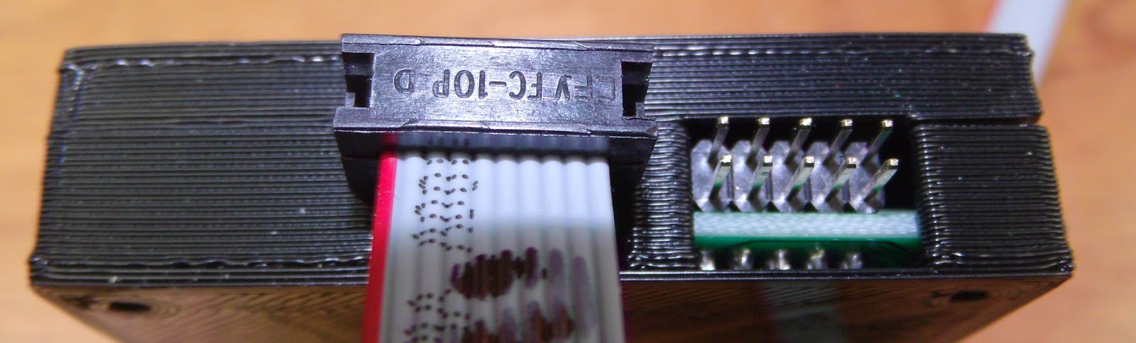
clearance for the IDC connectors needs moving up
Overall the following issues were noted:
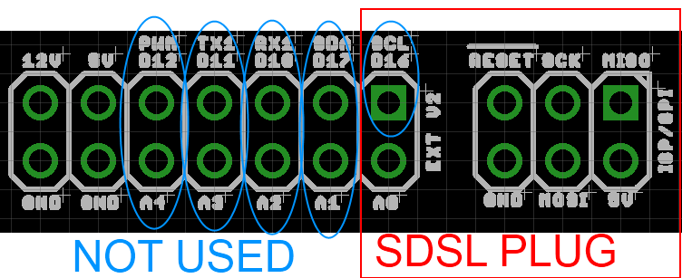
- The holes for the IDC plugs for the cables need to be wider and higher up in the case, easiest to replace with a single cutout.
- The box spacer used as a support in the back interfered with the back of the LCD
- To hold the board more rigidly some supports are required - the corners are the easiest place for these.
Fixes:
Change the IDC header dimensions, only one "header" needed in the model now:
//these are much bigger on z than the actual headers for clearance
idc_y_x=16; //not all will be within case
idc_y_y=37.9;
idc_y_z=6.39+2.5;
idc1_offset_x=128.4;
idc1_offset_y=18.1;
idc1_offset_z=1.61;
Remove the box spacer and add supports to the front and back:
module back() {
side=8; //for the supports
difference(){
union(){
difference(){
translate([-shell_width,-shell_width,-shell_width])
cube([pl_x+shell_width*2,pl_y+shell_width*2,shell_split_z+shell_width]);
translate([-clearance,-clearance,-clearance])
cube([pl_x+clearance*2,pl_y+clearance*2,shell_split_z+clearance+0.01]);
LCD_assembly();
}
//corner supports
for(i=[-wall_width,pl_y-side+wall_width]){
translate([-wall_width,i,-shell_width])
cube([side,side,8.75]);
translate([pl_x-side+wall_width,i,-shell_width])
cube([side,side,4.35]);
}
//additional support
translate([lcd_board_x-side,-wall_width,-shell_width])
cube([side,side/2,8.75]);
}
case_screw_holes(false,0);
}
}
module front() {
side=8; //for the supports
difference(){
union(){
difference(){
translate([-shell_width,-shell_width,shell_split_z])
cube([pl_x+shell_width*2,pl_y+shell_width*2,shell_top-shell_split_z +shell_width]);
translate([-clearance,-clearance,shell_split_z-0.01])
cube([pl_x+clearance*2,pl_y+clearance*2,shell_top-shell_split_z +clearance]);
LCD_assembly();
}
//corner supports
for(i=[-wall_width,pl_x-side+wall_width])
for(j=[-wall_width,pl_y-side+wall_width]){
translate([i,j,shell_split_z])
cube([side,side,shell_top-shell_split_z+wall_width]);
}
//additional supports
for(i=[-wall_width,pl_y-side/2+wall_width]){
translate([lcd_board_x-side,i,shell_split_z])
cube([side,side/2,shell_top-shell_split_z+wall_width]);
}
}
case_screw_holes(false,shell_top+shell_width);
}
}
The final case:
Step 5 - Optional Extras
For models I use often or that go through many iterations where I want to quickly change between different parts it makes sense to simplify the selection of what part of the model to display. At the top of the scad file I have:
///////////////////////////////////////////////////////////
//front, back or Assembly
///////////////////////////////////////////////////////////
side=2; //1 = front, -1 = back 2=printing layout -2 Electronics module 0=assembly model
///////////////////////////////////////////////////////////
//front, back or Assembly
///////////////////////////////////////////////////////////
side=2; //1 = front, -1 = back 2=printing layout -2 Electronics module 0=assembly model
///////////////////////////////////////////////////////////
This then determines what is rendered using a list of if statements used because, annoyingly, OpenSCAD does not appear to support a "switch" statement.
///////////////////////////////////////////////////////////////////////////////////////
// front
if (side==1)
{
front();
}
// back
else if(side==-1)
{
back();
}
//Printing plate
else if(side==2)
{
translate([shell_width,pl_y*2+shell_width*4,shell_top+shell_width])
rotate([180,0,0])
front();
translate([shell_width,shell_width,shell_width])
back();
translate([pl_y*0.5,pl_y*1.5+shell_width*2,shell_width])
knob_assembly(click_encoder_knob_dia/2);
}
//Electronics
else if(side==-2)
{
LCD_assembly();
}
//assembly
else
{
back();
front();
LCD_assembly();
translate([click_encoder_offset_x,click_encoder_offset_y,wall_width+ click_encoder_shaft_y+click_encoder_z-2])
knob_assembly(click_encoder_knob_dia/2);
}
///////////////////////////////////////////////////////////////////////////////////////
Thus changing one number allows you pick the render you want:
That's all for now - I hope to get a blog post out about the PanelOne itself soon.
Subscribe to:
Posts (Atom)


