Showing posts with label 3D printer. Show all posts

Sunday, 25 October 2015

Mini Kossel: Think3dPrint3d Release 3


Think3dPrint3d Mini Kossel Release 3

We have been selling our version of the Mini Kossel delta 3d printer for 15 months now. As is the nature of RepRap projects it has evolved along the way. We have marked these tweaks and upgrades and improvements as different versions of our kit and we are now ready to release our 3rd version - the Think3dPrint3d Mini Kossel Release 3. Though it builds on our other upgrades it is by far the most significant revision yet.

More detail is set out below but in summary we are switching to 32 Bit Duet Electronics, 20x20 extrusions, IR probing for true autocalibration, as well as some other more minor improvements to the usability or ease of assembly of the printer. Of these the single biggest change is using the Duet electronics with David Crocker's improved RepRap Firmware which allows for segmentation free delta printing and easy autocalibration.


Since David implemented delta support in the RepRap Firmware we have had many enquiries about buying the kits with the Duet (and some customers chose to help out as unofficial beta testers). It has taken until now for us to bring everything together into a kit form, including thdetailed documentation, to ensure builders will get the same great experience assembling this version as the previous ones.


Improvements in detail


Electronics


The Duet is a high powered 32 bit ARM-Cortex-M3-based 3D printing electronics solution which runs the powerful RepRap Firmware; more on this and the web interface later. With our kits in mind we designed a new 5-channel version of the Duet board with all the connectors, switches and power LEDs along one side. This allows for the electronics to be neatly mounted in the base of the printer with the USB, Ethernet, SD card, switches and power LEDs still fully accessible:


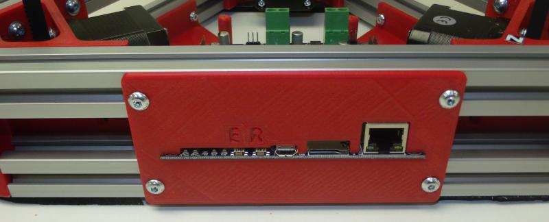
Duet 0.85 mounted in the Mini Kossel base showing accessibility

The new Duet V0.8.5 also has 2 extruder channels and so allows an easy upgrade path to dual extruders without an extension board, like the RAMPS in previous versions of the Mini Kossel, but unlike previous 4-channel Duets.


RepRap Firmware and Web Interface


David Crocker's RepRap Firmware takes advantage of the ARM chip's 32-bit processing power to provide true segmentation-free delta movement for improved smoothness and accuracy. Unlike most 8-bit firmware like Marlin, RepRap Firmware is precompiled and there is not normally any reason to modify or recompile it. The firmware is easy to configure with all the settings controlled through Gcodes in simple text configuration files. David has documented the setup of the configuration files in some detail on the RepRap wiki, for Cartesian printers, Delta printers and CoreXY printers.

The Ethernet support allows direct connection to a network or ethernet port on a laptop, or connection via Wifi. The web interface by Christian Hammacher is simple yet powerful and can be run on any device that is on the same network as the printer.


RepRapFirmware Web Interface running on Duet 0.8.5

I have taken to using my phone to control my printers:


RepRap Firmware Web interface on an Android Phone

20x20mm extrusions


These provide increased frame stiffness and allow the use of T-slot nuts which can simply be dropped into the extrusion channels when required, making assembly much easier.

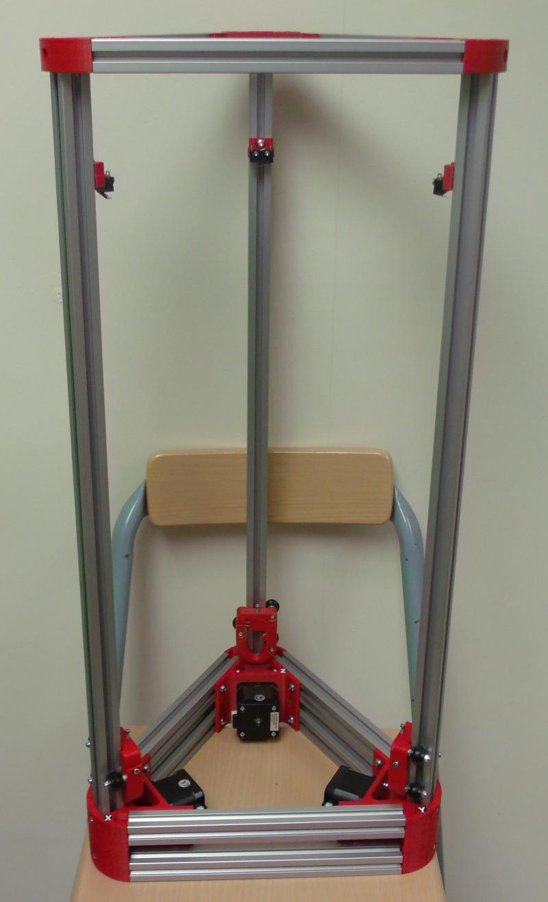
Mini Kossel part way through assembly showing 20x20 extrusions


Frame assembly is greatly simplified with T-slot nuts

Differential IR Probe


David Crocker also developed a really great mini IR probe which, when combined with the functions within RepRap firmware allows for quick and accurate printer setup and calibration.


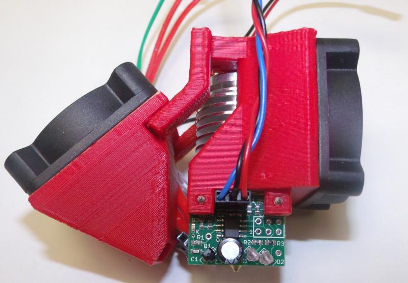
Hot end assembly showing DC42's differential IR probe mounted next to the E3D V6 heater block.

Below is a video showing the probe in action:


Other Improvements


To further simplify the printer wiring we designed an effector wiring breakout PCB
AppA-R13-hotend-PCB.JPG
Effector breakout PCB
Breakout PCB connected to hotend, IR probe, fans and wiring loom

The extruder and E3D V6 hot-end are preassembled and tested. 

AppA-R07-extruder.JPG
Assembled and tested extruder
AppA-R14-V6.JPG
Assembled E3D V6

While the majority of our customers have had no issues since we switched from the JHead to the V6 in Release 2, a few have struggled with the V6 assembly. As this kit is designed for hassle free assembly we want to eliminate all the potential issues. The V6 is assembled, heated to 290C and the nozzle tightened in accordance with E3D's recommendations.

We have included a top mounted spool holder for some time now, along with other tweaks and improvements suggested by our customers. For a full specification of the kit see our website.

Open Source Hardware.


As with everything we do the changes to the printed parts are available on our Github.

More to come!


We are also finalising the design and kit contents, and working on the documentation for a much larger Kossel, based to a large extent on David Crocker's supersized Kossel. It will optionally have a E3D Cyclops/Chimera dual extrusion hotend, 24V power and a massive 300mm diameter by ~480mm high print area. If you are interested in getting your hands on a Beta Kit then feel free to email us! Update 17 November 2015 - all 10 beta test slots have now been taken.

Wednesday, 24 September 2014

More Mini Kossel Updates

After nearly 4 months of supplying Mini Kossel kits we have had a lot of fantastic feedback from all the makers who have put the kits together. This is the third post on additions, changes and improvements (the first one is here, and the heated bed one here).


Simple second extruder fan mount


We have had a number of requests for a solution to allow a second, PWM controlled fan to blow on the part being printed, so I designed this modified J_head extruder mount:


This mounts on the end effector plate in the same way as the original one, with the exception that it is rotated by 60 degrees (one hole) to allow the z-probe to clear the second fan:


To minimise the air blowing on the heated bed from the existing, always-on, fan cooling the thermal break on the J-head, I added a strip of aluminium tape to the bottom of the always-on fan mount. The tape can withstand the hot-end temperature so I sealed all the way to the hot-end heater block insulation.


As the fan mount has to be rotated 60 degrees to allow the probe to clear the fan, one of the probe mount screws needs a nut adding:


The second fan is prepared with a male connector pin so it can be plugged and unplugged at the same point as the rest of the end effector wiring loom. In the long run the end effector wiring loom may move to a 2x5 pin plug.


The screws self tap into the plastic of the mount.


The fan wiring follows the same route as the remainder of the end effector/hotend wiring loom, with a plug lined up with the existing plug:


It connects to the RAMPS via screw terminal D9, between the extruder and heated bed (not connected in the picture below), allowing for PWM control when Motherboard number 33 is selected within Marlin configuration.h.


No firmware changes should be required from the standard setup and the cooling settings within Slic3r and Cura will turn the fan on after a specified number of layers.

The source files for the updated hot-end fan mount are on Github. and its also a "thing" on Youmagine!

New PSU for Heated Bed


After an issue with sourcing reliable and economical high current laptop power supplies, James Clutterbuck suggested the Dell DA-2; a 12V 18A power supply:


This beast is capable of providing enough power for the whole printer and heated bed so from now on complete printer kits ordered with heated beds will be supplied with just this power supply. Unfortunately although the DA2 is supplied with what appears to be a 2x4-way Molex Minifit plug, the housing doesn't mate correctly with the standard Molex 2x4 Minifit socket, and so needs to be changed (part numbers below).


Roland designed a new face plate that accommodates the Molex socket along with a power switch and the USB plug.


The power supply cable is wired to both sides of the RAMPS plug:


The assembled faceplate installed:


The documentation will be updated shortly. The source files are available on our Kossel Mini Repository on Github (USB-power-8way-V2). If you want to source the parts for the upgrade, along with the printed plate, you need:

Dell DA-2 Power supply (12V 18A)
8 way connectors: Molex 39-01-2080 and 39-01-2081
16AWG crimp pins for molex 39-00-0078 and 39-00-0082.
Standard case rocker switch such as this one.


Marlin improvements


The Think3dPrint3d Kossel fork of the Marlin firmware is available on github and comes pre-configured as a good starting point for Marlin on a Mini Kossel. I have recently implemented a couple of improvements. Firstly David LapeÅ¡ pointed out this feature request/ bug fix for the main version of Marlin which allows for negative position numbers to be correctly displayed on the PanelOne screen:


The second change is to add 4 menu items for filament management. Within the "Prepare" menu you can now choose to prime or retract the filament by a small amount (default 3mm) as well as either load or unload the filament completely (default 560mm).


The default values can be changed within configuration.h, line 399 onwards:

#define EASY_LOAD
#define BOWDEN_LENGTH 560
#define LCD_PURGE_LENGTH 3
#define LCD_RETRACT_LENGTH 3
#define LCD_PURGE_FEEDRATE 200
#define LCD_RETRACT_FEEDRATE 600
#define LCD_LOAD_FEEDRATE 500

#define LCD_UNLOAD_FEEDRATE 500

You can also set the feed rate for each action (in mm/minute)

This based on Lajos's changes to Marlin for the Tantilus printer, I changed his implementation to make it work with the delta firmware and simplify the options a bit.

You can upgrade to these changes by downloading the Think3dPrint3d version of Marlin and uploading it. Make sure you copy across any changes you have made to configuration.h such as the Z height and delta radius after calibration.

Sleeker cable management


Mark Burton has added "Go Faster" stripes to his Kossel mini in the form of these extrusion insets, which nicely hide away the endstop cables.


4 of the strips fit in each extrusion tower. The scad and stl files are on github.


 Thanks to everyone who has sent feedback and design improvements!

Wednesday, 27 August 2014

F3D, a prototype 3d printer for food

Back in February I was contacted by Hillel Baderman, one of a group of 4 talented undergraduates from Imperial College London. They were developing a novel 3d printer capable of printing, as well as cooking, food pastes.


CAD render of the 3d food printer design - all images from www.f3dprinter.com

At the time several solutions existed for printing with different pastes, the most well known in the the RepRap world was RichRap's Paste extruder, and there was a great writeup of Unfold Fab's work with clays in issue 3 of the RepRap magazine. For this project they wanted to go a couple of steps further, with 3 paste extruders and have the printer cook the extruded food. 

Additionally, they wanted the printer to be made largely from open source material in spirit of the RepRap community. The Duet+Duex4 combo provided an ideal solution for their food-printing/cooking project, as it allows printing with up to five different extruders. They edited the RepRap firmware to suit a paste extrusion system and added a relay to control the Halogen oven.

Here is a video of it printing "F", "3", "D" letter cookies:


Cooking is achieved using a 1400W halogen oven which allows for fast heat up and a simple control mechanism.

The crowning glory of the prototype system is the ability to print a pizza; dough, tomato puree and soft cheese!


The three stages to printing and cooking the pizza.

Their prototype proved to be very successful – their final version printer could print the pizza in just 20 minutes and it certainly looks more appetizing than some of my student creations ever did.

They published the full project work online at http://www.f3dprinter.com/. A great achievement in a short time and I really hope they can continue to work on this and take it further!

Thursday, 26 June 2014

Kossel Mini - feedback and tweaks

After a manic month or so shipping Kossel Mini Kits we have been getting loads of feedback from those building the printer. A lot of the feedback was around the documentation which we have continued to adapt and develop, trying to ensure that if we get asked a question a couple of times we answer it in the documentation. Please keep this feedback coming - we really appreciate it!


Endstop trigger point adjustment


After re-reading minow's very helpful blog on in depth calibration we decided to make a minor change to the endstop trigger function. Previously the endstops triggered on the top of the X,Y and Z carriages:


These have been replaced with slimmer endstop mounts and a modified Delrin V-roller carriage adapter with M2.5 socket cap screw:


This means the endstop trigger point can be finely adjusted in order to level the bed very accurately.

The Delrin V-roller carriage adapter is modified from Haydn Huntley's design, while the slim line endstops are from Johann's original design. The modified files are available on our Github.

The changes can be retrofitted to existing Kossel Minis by simply drilling a hole for the M2.5 to self tap into and printing the thinner endstop mounts. It is fiddly to drill the holes in situ, even using a hand drill, so one Delrin V-roller can be removed to allow the carriage to be removed for easier access. We will shortly publish a new chapter of our Mini Kossel build manual showing this process in detail.


Endstop Trigger point calibration procedure


This process will be incorporated in the manual as soon as we are confident we have explored any downsides to this approach.
The endstops on the X Y and Z pillars should all trigger at the same distance from the bed. This procedure will show how to set these.

Start by using a ruler or measuring tape to set them approximately (within 1mm) at the same distance up the pillars.

Next fine tune each endstop trigger point in turn. This is an iterative process as each adjustment alters the others slightly. First adjust the Z height in the Marlin firmware to a few mm more than it needs to be and upload the firmware:


#define MANUAL_Z_HOME_POS 255


Then work through steps 1-5 below. Note you should do this with the extruder (and heated bed if you have one fitted) at the printing temperature.

  1. Find the X axis endstop trigger point
    1. Home the printer (G28)
    2. Move the extruder to just in front of the X pillar (G1 X-76 Y-43 Z10 F7000). The tip should be approximately 5mm above the bed.
    3. Lower the extruder using Pronterface until a piece of standard 80 gsm printer paper just drags on the nozzle.
    4. Make a note of the Z height using M114:

SENDING:M114

X:-76.00Y:-43.00Z:5.10E:0.00

  1. Adjust the Y axis endstop trigger point
    1. Home the printer (G28)
    2. Move the extruder to just in front of the Y pillar (G1 X76 Y-43 Z10 F7000). The tip should be approximately 5mm above the bed.
    3. Lower the extruder using Pronterface until a piece of standard 80 gsm printer paper just drags on the nozzle.
    4. Check the Z height using M114; the aim to get this to the same value as that recorded for the X axis.
    5. Adjust the M2.5 screw on top of the Y carriage to raise or lower the trigger point (a 360 degree rotation of the M2.5 screw will give a 0.45mm change in trigger point)
    6. Repeat steps a. to e. until the Z height checked in step d. is the same as that recorded for the X axis
  2. Adjust the Z axis trigger point
    1. Follow the same process as step 2, using (G1 X0 Y85 Z4 F7000) to place the extruder in front of the Z pillar
  3. Work around steps 1-3 again because if large changes were required they will noticeably influence the set points of the other axes. Once they are within 0.1mm of each other, move to the next step
  4. Finally we can set the correct “0” point for the centre of the bed.
    1. Home the printer (G28)
    2. Move the extruder to just above the center of the bed (G1 X0 Y0 Z10 F7000)
    3. Lower the extruder using Pronterface until a piece of standard 80 gsm printer paper just drags on the nozzle.
    4. Note the Z height using M114

SENDING:M114

X:0.00Y:0.00Z:5.20E:0.00

  1. Subtract  this Z value from the one set for the manual Z home position at the beginning, change this in the Marlin firmware and re-upload the firmware. In this example it was 255-5.2 = 249.8

#define MANUAL_Z_HOME_POS 249.8
The endstop trigger points are now all within 0.1mm of each other and Z “0” is within 0.1mm of the top of the bed.

The next step is to calibrate the delta radius - Minow's blog outlines the process very well (see step 3).


New Extruder Mount


One of our customers, elmuchacho on thingiverse, has shared a number of designs as upgrades for the Mini Kossel. This is his extruder mount (his picture, then Think3dPrint3d's picture)


This extruder mount holds the extruder more firmly to the frame than the original Think3dprint3d zip tie version. It uses a nut threaded onto the PTFE tube rather than the pushfit connector (top picture).The new mount is shared by elmuchacho on thingiverse and tinkercad. He has also shared a version that uses the pushfit connector supplied with our kits.

To complement this I have reverted part of the extruder block to use the mounting screws and taken the opportunity to make a few other minor tweaks to improve printability - it's also available on the Think3dprint3d github.


Vibration damping


I have noticed a slight chatter in the Traxxas linkages. This is a common issue and the jury is still out on if it noticeably affects the print quality. That said, reducing this definitely makes the printer quieter. One solution is to use rubber bands:


These clips were also designed by elmuchacho: http://www.thingiverse.com/thing:371998

Dust is also using a similar idea on his Mini Kossel build (He is not building one of our kits but a similar printer).


Heatbed


We have confirmed the design for the heatbed (Kapton heater on Alu plate with insulation underneath). We are now just waiting for parts to arrive in bulk before we go ahead and offer them for sale. They will be offered at a discount to existing Mini Kossel customers and as an upgrade/stand-alone item as well. The details will follow in a separate blog post.

Sunday, 1 June 2014

Kossel Mini and More


Our Mini Kossel is a version of the excellent Kossel delta robot printer from Johann Rocholl, the designer of the original Rostock delta. It's very quick and easy to put together and relatively economical to source parts for. We have designed some additional parts and incorporated a number of variations from around the community. The changes we have made are described below and all the additional source files are available on Github (look in the T3P3 additions directory)

The Mini Kossel can be bought as a kit or assembled from www.think3dprint3d.com  There are 5 colours in stock or we will print you a set in any custom colour we can source and print. All our parts are printed in ABS on our Mendel90 Lasercut production printers which continue to churn out excellent-quality parts every day after almost a year in service.


Linear Rails v Rollers


The initial Kossel design used linear rails


Picture (c) hiwin.com
These are great but add significantly to the cost. Using rollers on the aluminium extrusions themselves has been suggested in a number of places:

http://www.electronhacks.com/2013/12/kossel-mini-3d-printer-vertical-movement-tutorial/

http://www.thingiverse.com/thing:308369

and this comparison here: http://www.builda3dprinter.eu/rails-wheels/.

These convinced us to try the roller based option. As we are using Mitsumi aluminium extrusions we got Delrin rollers precision machined:


After many hundred of hours printing the bearings and extrusions are not showing visible wear. The only lubrication we have used is a spray of light oil containing PTFE (for example GT85). It is very simple to tighten the adjusting capscrew to adjust the pre-load and take up any slack if they do wear.

Johann is looking into using recirculating Delrin balls directly on the extrusion as well - well worth following up as and when time permits. Delrin balls are quite pricey, though, but it would be awesome if Airsoft BB pellets turned out to work well. The best carriage for these turned out to be Haydn Huntley's.


RepRapPro mini extruder


This extruder has been proven over many thousands of hours, both on RepRapPro's Mendel and Huxley printers and on our Mendel90 Lasercut multi extruder machine.


We modified this slightly to use easily obtainable pushfit bowden fittings and made a our own version of the quick and simple zip tie mount to fit to the extrusion:


Power and electronics mountings

To keep the kit as simple and user friendly as possible we designed a USB and power plug plate:


That provides a neat interface with the RAMPS in the base of the printer. The non-heated bed version uses a single 5 amp laptop style power supply. We are investigating options for the heated bed version but one being considered is an extension of this plate with another plug for a heated bed power supply. The RAMPS is mounted on another simple plate:


The picture also shows some simple tabs to keep a round glass mirror plate fixed securely using M3 penny washers.


Filament management

A reel holder and filament guide complete the kit:


Build Manual

We have written a comprehensive Kossel Mini Assembly Manual for the kit which we hope will become a useful resource for all. We would really welcome feedback on the manual and suggestions for additional information to add. 

Prints

One of the Mini Kossel beta testers did these prints of the EggO egg "thrones" by mageli which are awesome. 


PanelOne LCD

Following on from the case design tutorial in SCAD here is more information of the PanelOne, a simple LCD controller for RAMPS. It is optimised for those who want to rout/etch a single sided PCB with only through-hole components. It also uses widely-available 10-way IDC ribbon cables.


The more fiddly elements of the SD card socket and logic level converter are left to an optional, and generally available, daughter board such as this one from adafruit:


image from adafruit.com
or this one:
image from hobbytonics.co.uk

The circuit board itself is designed in KiCAD as a single sided board, and was originally designed for Sumpod who commissioned us to design a board that could be routed on a PCB mill and fitted the dimensions of their printer enclosure.


In keeping with the simplicity of the design there is no adaptor board required at the RAMPS end as the pinouts are arranged to match with the AUX2 and AUX3 headers.


The complete KiCad files for the PanelOne are available on github.

Coming Soon

Watch this space... we are working on adding a heated bed and an interesting twist on multiple extruders!