Update: The Panelolu2 has replaced the Panelolu. It is much quicker to install, has adapter boards to no messing with cables and uses less pins. The blog post with the information is here, it is available to buy in our webshop.

Panelolu is an LCD and rotary encoder with a click button control solution which derives from the PanelMax Prusa by tommyc. It allows control of a 3D printer running Marlin firmware and Sanguinololu or similar electronics directly without having to have a computer connected. Stand-out features are the ability to start and stop prints, control print speed while printing and change many calibration settings - saving these to the memory on the ATmega 1284 (EEPROM) so they are persistent if you turn the printer on and off. Continuing with tommyc's design the panelolu has mounting brackets for the Prusa mendel or other threaded rod based printers. The brackets are separate from the enclosure so they can simply be replaced with a different design for a different mounting solution.

The Panelolu is designed to use as little soldering as possible (if the breadboard comes pre-assembled and the LCD with plugs fitted then no soldering is required at all) and to allow an easy upgrade path. It uses the SDSL card reader, so if you already have one there is no need to get another. Rather than soldering wires directly to the LCD, headers have been fitted so future changes can re-use the LCD simply.


What's in the case
The schematic is a little tangled but each wire can be traced from the Sanguinololu - through the 24 way IDC connector and ribbon cable to its final destination in the enclosure. A 22 way IDC connector would have worked fine but they're are hard to find so we use a 24 way and don't plug in pins 23 and 24.

Assembly instructions
Step 1 - Assemble the tools and components
The Panelolu can be assembled with a few basic tools:
- Allen Key for the M3 socket head fastenings
- Cross head screw driver for the SDSL and breadboard mounting screws
- Small needle nose pliers for crimping connectors
- wire cutters
The enclosure is on thingiverse, as a OpenScad file and STL.
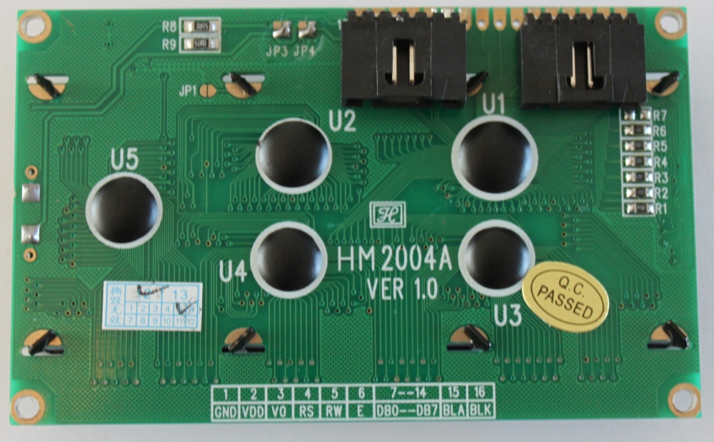
The components are as in the picture below:

The rotary encoder is this one, the reset switch and pots are very generic. Most LCD panels come with mounting holes for M2.5 screws, but I prefer to drill these out slightly and use M3, the enclosure has M3 holes but they should work ok with M2.5 if you prefer to use that.
Step 2 - Assemble the breadboard and the LCD connectors.
(if you get them pre-assembled ignore this step and move to step 3!).
UPDATE: We now supply Panelolu kits with circuit boards - the breadboard instructions below are only necessary if you want to source your own components.
Note these instructions are for a the breadboard assembled with the click encoder on the right of the panel as you look at it from the front - If you want it on the left then mirror the layout.
The schematic contains the circuit diagram for the breadboard. It is laid out to minimise the number of jumper wires required - many of the connections can be bridged.

An absolute minimum of 4 rows and 29 columns are needed in order to fit the screw holes in. The components are placed as shown:

and from underneath:

As shown on the left of the picture of the underside the encoder's mounting legs have been bent round to hold it securely to the board.
The picture below shows the different circuits.

To start with make the direct connections for "ENC 1", "CONT", "BRT" and "RST".

Next use small lengths of wire to make the remaining connections. Leave as little excess wire as you are comfortable with, as it will be easier to fit into the housing:


Now do the LCD: Solder the 6 way right angle headers onto the LCD pins 1-6 and 11-16. The picture shows shrouded headers but normal right-angle pin headers are fine.
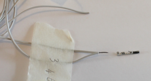
Using the cable numbering from the cable picture, you are connecting wires number 13-22 into the SDSL plug. Note the polarity as shown in the pictures. Ensure you leave at least 10 cm of length on the cable past the plug, as this will make wiring the remaining connections easier.


The easiest way to fit IDC connectors without a proper (and expensive) tool is to use a small vice. Ensure the cable is in square in the connector and the the pressure applied by the vice is even - don’t rush this bit! The back should click into the connector.

The 24 way IDC socket is fitted in the same way; ensure you use pins 1-22 of the socket (a 22 way socket would be even better but hard to find)


Step 4 - Fitting the crimp connectors.
There are three
6-way connectors and a 2 way connector that use crimp terminals. These
can be crimped using small needle nose pliers if you don't have a
crimping tool. Nophead has an excellent video on how to crimp them.I found it easiest to identify the wires for each connector from the circuit diagram and the photo below and cut them to length before fitting the pins. Be sure not to make them too short!

The 12V and ground pins on the expansion header are not used by Panelolu but I have left the wires so they can be connected to something else if required. The pieces of wire offcuts in the picture are used to make the connections between the various sockets (as shown in thicker green wires in the schematic near the top of the blog post). Leave these a little longer than the minimum distance to assist with assembly at the end. On some pins you will need to connect two wires to one pin:

Once complete the assembled cable should look like this:

Step 5 - Assemble
It is easiest to first screw on the SDSL socket and the bread board with the LCD in position, then the strain relief and finally bring the two halves together to plug in the 4 connectors. Although the SDSL itself can be fitted once completely assembled it's easier to fit it at this stage ensuring the orientation is correct.
Close it all up, being careful not to trap any wires. The length of socket setscrews used will depend on the mounting solution. There is a 5th small screw to hold the bottom of the case below the click encoder closed.
I will do a second post about mounting once I have some better pictures of it mounted on a prusa and my Mendel 90 mounting solution sorted.
Firmware
Firmware
In order to use this you need a 1284P in your Sanguinololu and the Marlin firmware needs the changes that I mentioned in my previous post and have pasted here as well:
Configuration.h
Line 34:
#define MOTHERBOARD 62
Line 190-205:
#define EEPROM_SETTINGS
//to disable EEPROM Serial.....
// please keep turned on if you can.
#define EEPROM_CHITCHAT
//LCD and SD support
//#define ULTRA_LCD //general lcd support, also 16x2
//#define SDSUPPORT // Enable SD Card Support in Hardware Console
#define ULTIPANEL
#ifdef ULTIPANEL
#define NEWPANEL //enable this if you have a clicencoder panel
#define SDSUPPORT
#define ULTRA_LCD
#define LCD_WIDTH 20
#define LCD_HEIGHT 4
Configuration_adv.h
Line 163:
//#define SDCARDDETECTINVERTED pins.h, making sure to be within the sanguinololu pin definition part of the file. For my pins.h this was lines 557 - 657. I added the following 34 lines, copied from the RAMPS section of the pins.h
#ifdef ULTRA_LCD
#ifdef NEWPANEL
//we have no buzzer installed
#define BEEPER -1
//LCD Pins
#define LCD_PINS_RS 4
#define LCD_PINS_ENABLE 17
#define LCD_PINS_D4 30
#define LCD_PINS_D5 29
#define LCD_PINS_D6 28
#define LCD_PINS_D7 27
//The encoder and click button
#define BTN_EN1 11 //must be a hardware interrupt pin
#define BTN_EN2 10 //must be hardware interrupt pin
#define BTN_ENC 16 //the switch
//not connected to a pin
#define SDCARDDETECT -1
//from the same bit in the RAMPS Newpanel define
//encoder rotation values
#define encrot0 0
#define encrot1 2
#define encrot2 3
#define encrot3 1
#define BLEN_C 2
#define BLEN_B 1
#define BLEN_A 0
#endif //Newpanel
#endif //Ultipanel
Finally..
Ordered the kit, built it, made the changes in Marlin and uploaded. All worked and it all took less the 4 hours from start to finish. It's a very good kit! Love it already. Printing case soon. Thank you!
ReplyDeleteThanks for the kit. I love it and use it all the time.
ReplyDeleteI have two questions:
1. When I turn the knob clockwise the the speed goes down instead of up - not sure why. Rather than attempt a rewiring job, is there a simple firmware change I can apply to make it go the other way?
2. I like using the Flow: setting to tweak my print quality on the fly but I have no idea what the numbers relate to. For example, mine started at 45 but I found I got much better prints if I turned it down to 36. On the computer I use M221 S90 to reduce the flow to 90%, but on the click controller I don't know what the numbers mean. Any ideas?
Hi Rich
DeleteI am glad you like it!
1. I need to update the code above. If you swap the pin allocations around then the other direction is +'ve. So in pins.h if anti clockwise is positive with the code above, change it to:
//The encoder and click button
#define BTN_EN1 10 //must be a hardware interrupt pin
#define BTN_EN2 11 //must be hardware interrupt pin
and the direction will change.
2. The flow setting is the E-Steps for example I use a modified Wades with herring bone gears and an m8 hobbed bold so mine are set between 650 and 800 depending on the printer (different gear ratios and hobbing depth). If you use a direct drive extruder then it will be around the figures you mention I guess (but I don't have one yet so not sure). When you use S221 you are setting the percent, not the E-Steps, hence the disparity.
Hope that helps!
Tony
Thanks Tony.
ReplyDeleteThe first answer helps a lot - I'll definitely try that out.
The second, not so much. I have the same extruder as you on my Mendel90 and I recognise the 650 to 800 values for E steps/mm in both host software (Repetier Host) and firmware (Marlin).
What I still don't recognise is the numbers displayed for Flow on the LCD screen - 36 to 45 what?
Cheers
Richard
That is odd, on my screens I have 650 or similar. How new is your Marlin? I have not upgraded in a while, working on the if it ain't broken... theory but I am due an upgrade so I will try the newest Marlin and see if I get the same inscruitable flow values as you.
DeleteAll fixed now.
ReplyDeleteI found the answer here - https://github.com/ErikZalm/Marlin/issues/201
Changing the 'int xx=' to 'long xx=' in all the places at the end of the UltraLCD.pde file means it now displays E and Z steps/mm correctly.
Richard
Great! Thanks for passing the info on.
DeleteSnille on thingiverse has made a derivative case for this that added a PWR LED and stands, check it out here;
ReplyDeletehttp://www.thingiverse.com/thing:28332
Hi
ReplyDeleteGreat item. Idfeal for its purpose , there is also a group of small machine users that would benefit from this device but im not sure how to reconfigure it. For those using the arduino Uno and Mega units that drive 3 or more axis of small routers and millers would also like to dispence with the external PC. The display SD card and encoder fit the bill perfectly. Any ideas.
Clive
diyexpert@ymail.com
Hi loving the panelolu kit , however i have managed to break the 10way IDC socket , does anyone have a part number or link to a replacement part
ReplyDeleteHi Toushea, the part is by 3M, part no 4610-7050
Deletehttp://uk.mouser.com/ProductDetail/3M-Electronic-Solutions-Division/4610-7050/?qs=xQnIkPM%2fQr7h3ET4K5eCSWtiqeBUr3wmlX%252bYj1pAe4c%3d
You will have to pay shipping from Mouser. if you prefer we can provide a replacement for part+postage.
This comment has been removed by the author.
ReplyDeleteThis comment has been removed by the author.
DeleteHi Tony,
ReplyDeletevery nice kit! I got the shipment really fast (I live in germany) and got it working in about 4 hours with repetier firmware!
Works like a charm ... just have to find a microsd card to print standalone :)
Thank you
P.S.:
Lines that need to be edited for Repetier Firmware: (in uiconfig.h)
#define UI_DISPLAY_TYPE 1
#define UI_COLS 20
#else // Direct display connections
#define UI_DISPLAY_RS_PIN 4
#define UI_DISPLAY_RW_PIN -1
#define UI_DISPLAY_ENABLE_PIN 17
#define UI_DISPLAY_D0_PIN -1
#define UI_DISPLAY_D1_PIN -1
#define UI_DISPLAY_D2_PIN -1
#define UI_DISPLAY_D3_PIN -1
#define UI_DISPLAY_D4_PIN 30
#define UI_DISPLAY_D5_PIN 29
#define UI_DISPLAY_D6_PIN 28
#define UI_DISPLAY_D7_PIN 27
#define UI_DELAYPERCHAR 320
#endif
#define UI_HAS_KEYS 1
#define UI_ENCODER_SPEED 2
void ui_init_keys() {
UI_KEYS_INIT_CLICKENCODER_LOW(11,10); // click encoder on pins 47 and 45. Phase is connected with gnd for signals.
UI_KEYS_INIT_BUTTON_LOW(16); // push button, connects gnd to pin
// UI_KEYS_INIT_MATRIX(32,47,45,43,41,39,37,35);
}
void ui_check_keys(int &action) {
UI_KEYS_CLICKENCODER_LOW_REV(11,10); // click encoder on pins 47 and 45. Phase is connected with gnd for signals.
UI_KEYS_BUTTON_LOW(16,UI_ACTION_OK); // push button, connects gnd to pin
}
Hi Nikolai
DeleteGreat news, thanks alot for posting the Repetier Firmware modifications required. I have not played with this firmware but I have heard good things.
Tony
any idea in order to use sdramps on this wiring?
ReplyDeleteHey Saiful
DeleteThe SDRAMPS and SDSL are very similar, just the order of the pins is different. The design files are available from Kliment who designed them. SDSL: http://koti.kapsi.fi/~kliment/photos/sdsl/
SDRAMPS: http://koti.kapsi.fi/~kliment/photos/sdramps/
The SDRAMPS plugs into the AUX3 header on the RAMPS 1.3 board so you can see the order of the pins on the RAMPS page on the reprap wiki.
How to wire a Panelolu up to a RAMPS is discussed on this blog post:
http://blog.think3dprint3d.com/2012/11/panelolu-on-ramps-and-printrboard-issues.html
hope that helps!
Good day! I have melzi board (mono mendel by reprappro.com), and collected Panelolu (only threw the extra pins for sd) by you instructions, and don `t know where to connect the RS LCD output, melzi does not have pins PWM. It is possible at all to connect it to melzi?
ReplyDeleteHey Andry
DeleteCan you confirm if you are using a Panelolu or Panelolu2?
Cheers
Tony
I bild a Panelolu 1, from this article.
DeleteHey Andry
DeleteThe original Panelolu needs more pins than the Melzi electronica has spare on the expansion header. The Melsi has a built in fan etc which uses up additional pins, that is one of the reasons why I designed the Panelolu2 which reduces the number of pins required to run an LCD screen, check out this blog post for more info:
http://blog.think3dprint3d.com/2013/03/panelolu2-for-melzi.html
Cheers
Tony