The PanelOne LCD display and control panel was originally designed for RAMPS1.4, and that is still the most sensible way to use it as it uses two 2x5 IDC cables that are readily available. The PanelOne circuit board is designed to work with 3.3V and 5V electronics and this weekend I tested it with Sanguinololu (effectively going full circle back to the original Panelolu - just a lot easier to put together and use!)
This works fine, although you do need to be careful to plug the pins in correctly:
The correct pins for Sanguinololu are:
Wire number PanelOne Sanguinololu
Aux2
1 5V 5V
2 GND GND
3 EN B Rx1
4 EN A Tx1
5 LCD DB7 A4
6 LCD RS PWM
7 LCD DB6 A3
8 LCD E SDA
9 LCD DB5 A2
10 LCD DB4 A1
Aux3
1 Not Connected
2 Not Connected
3 CS A0
4 CLK SCK
5 DO MOSI
6 DI MISO
7 EN SW SCL
8 VCC 5V
9 Not Connected
10 Not Connected
This blog post has a good image of the location of each pin on the Sanguinololu, re-posted below:
The IDC cables are numbered with wire 1 being the red coloured wire.
This will work out the box with the T3P3 version of Marlin by enabling #SDSUPPORT and #ULTIMAKERCONTROLLER in configuration.h
The process followed can be adapted to use the PanelOne on any electronics that runs Marlin and has enough free pins. Do let me know if you get it working on another board!
This is the archive blog for Think3dPrint3d, please see Duet3d.com for up-to-date information
Showing posts with label Electronics. Show all posts
Monday, 20 October 2014
Monday, 30 December 2013
Duet FET, PSU and Stepper Driver Testing
This blog post is primarily a cut and paste from notes made during the testing of the Duet v0.3 (note the current version is 0.6). I have uploaded the design files for version 0.3 onto the archive area of the github project so the differences between the design tested in these pictures and the current design can be seen.
Normally I would try and get more detail into the post about the design decisions but that will have to wait until a later post.
FETs Testing
FETs are on by default when 3.3V regulator is disconnected as Vgs = 5V (same as when MCU turns FETs on), so software not required. (Note this setup has been replaced in version 0.6 with FETs off by default).
Tested with 10A load gives Vds = 32mV - therefore dissipating 0.32W
32mV at 10A = 3.2mOhm on resistance. As expected from datasheet.Temp measured at ~40C with thermal camera (ambient ~23C):
A 20A load would give 1.28W dissipation. i.e. 4 times as much as 10A, therefore expect 50-60C temp rise on FET from ambient. FET rated to 175C.
http://forums.reprap.org/read.php?340,285306
A great example of the benefits of releasing an open source design - really high quality feedback!
Normally I would try and get more detail into the post about the design decisions but that will have to wait until a later post.
FETs Testing
FETs are on by default when 3.3V regulator is disconnected as Vgs = 5V (same as when MCU turns FETs on), so software not required. (Note this setup has been replaced in version 0.6 with FETs off by default).
Tested with 10A load gives Vds = 32mV - therefore dissipating 0.32W
32mV at 10A = 3.2mOhm on resistance. As expected from datasheet.Temp measured at ~40C with thermal camera (ambient ~23C):
Track adjacent to FET (carrying input power) got marginally hotter, though nothing to worry about particularly but aim to increase track width on Duet v0.4.
PSU Testing
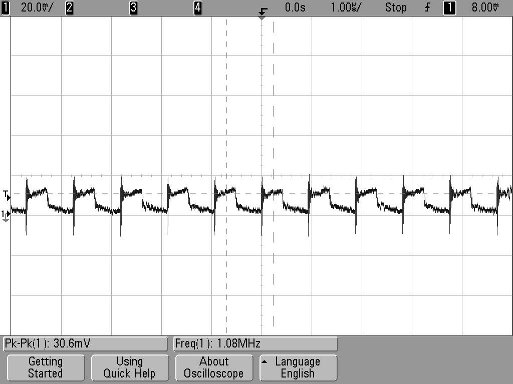
Perfectly happy at low loads (<750mA) (note the Arduino Due Power supply only dives a total of 800mA). 12-24V in, 4.98V out. Voltage ripple = ~30mVpk-pk (DC-20MHZ) See scope plot below:
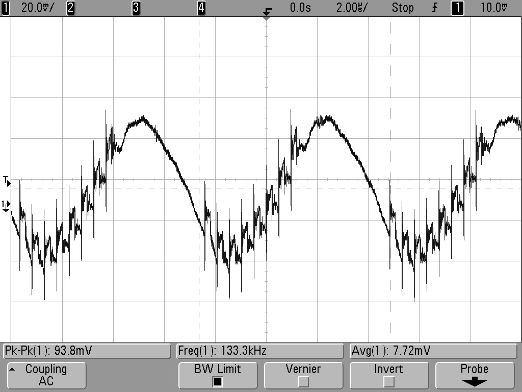
Marginally unstable with 1A or greater load and Vin >16V.
Voltage ripple = ~100mV (DC-20MHz). See scope plot below:

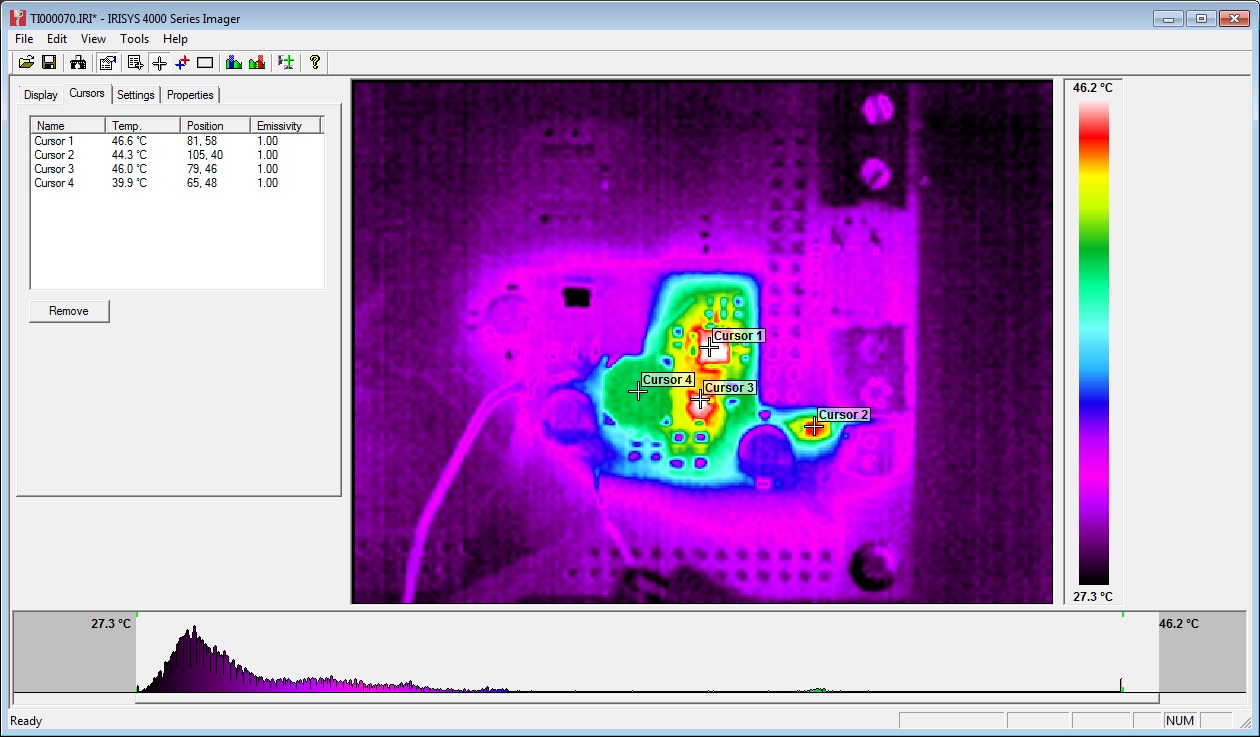
At 1A load, PWM IC temp = ~40C:

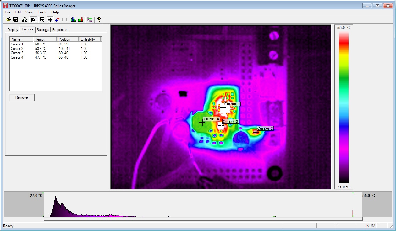
At 1.5A load, PWM IC temp = ~60C:

Further testing on 20/06/13:
Inductor L1 swapped from 22uH to 8.2uH. Tested 12V to 24V input and 0A to 1.5A output load.
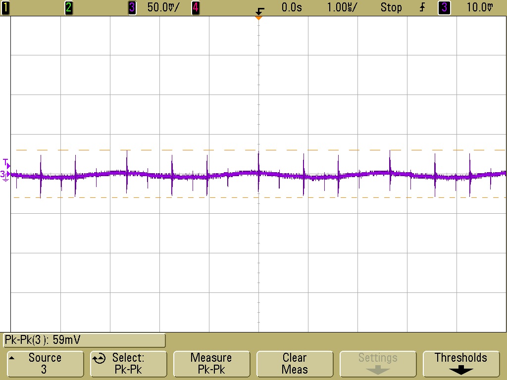
12V input, 1.5A load, voltage ripple+noise = ~60mVpk-pk (DC-20MHZ) See scope plot below:

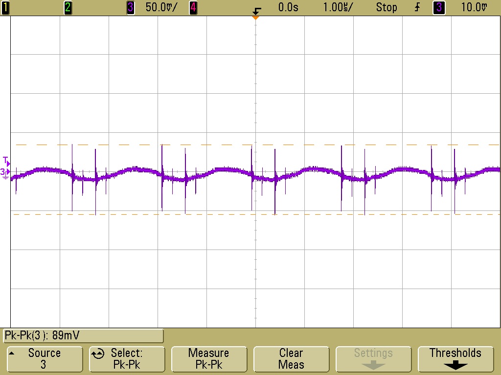
24V input, 1.5A load, voltage ripple+noise = ~90mVpk-pk (DC-20MHZ) See scope plot below:

Stepper Motor Testing
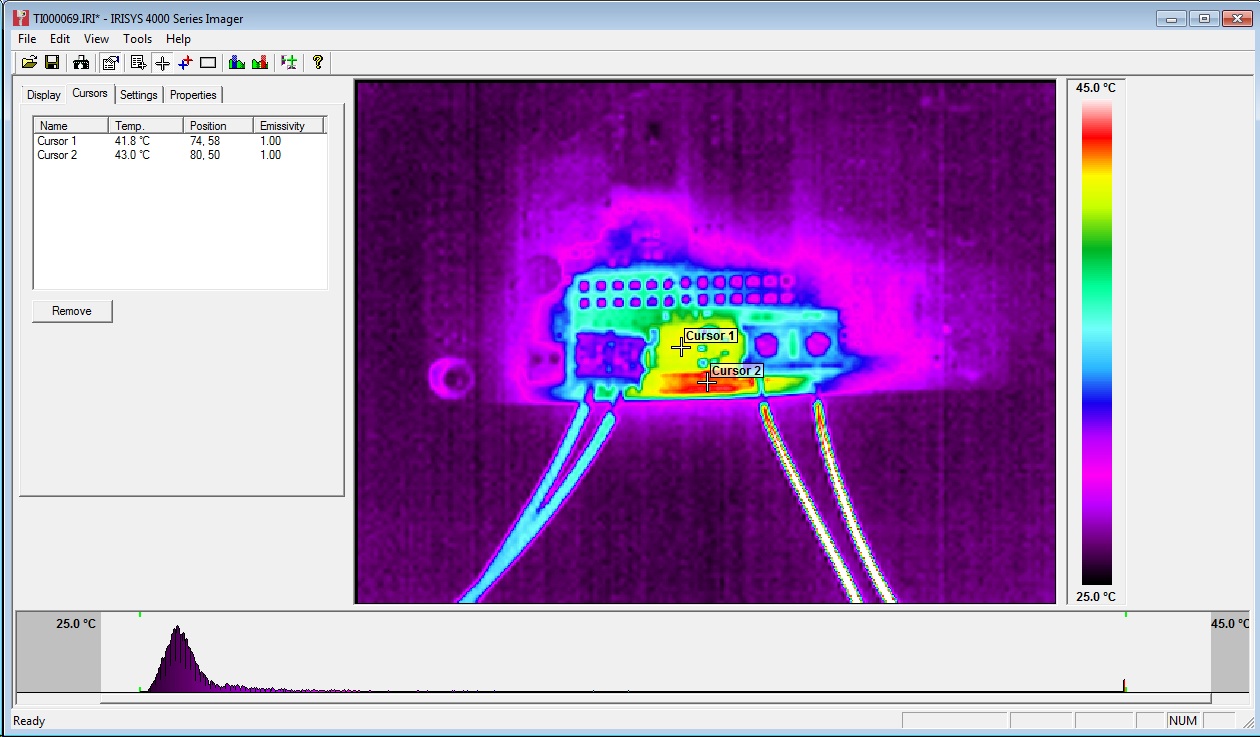
Initial testing completed using stepper.ino sketch. Timings changed to 10,000 for CW and 25,000 for CCW steps. An unloaded motor was run for 30mins with these step rates and then a thermal image was taken of Duet board. See below:

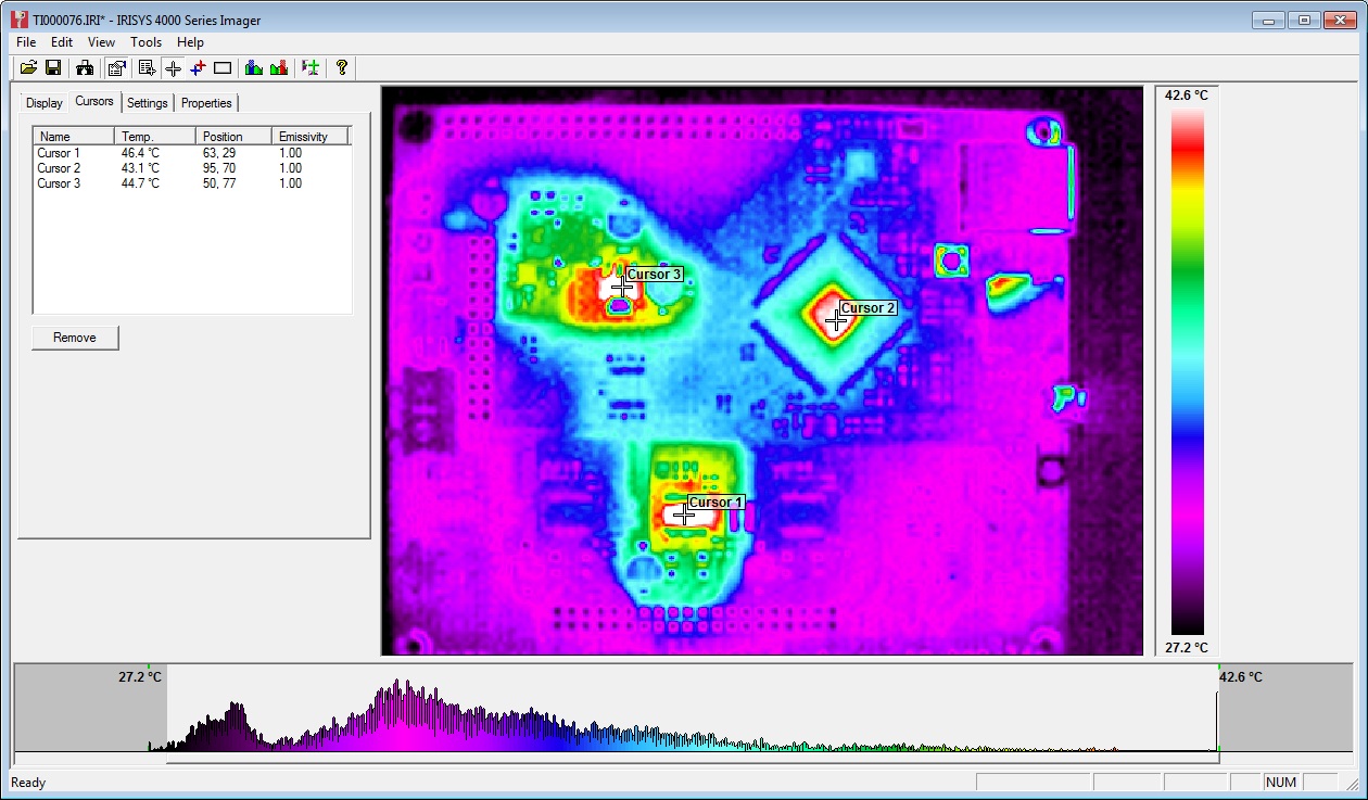
The three hot-spots seen in the image are the 3.3V regulator, the MCU and the stepper driver IC. All three showing temps of around 45C.
Note: Other random colourful spots are reflections off shiny surfaces - e.g. button switches and SD card slot.
Afterward
The main point of posting this now is to inform the discussion on the RepRap forums about potential improvements to the Powersupply:
A great example of the benefits of releasing an open source design - really high quality feedback!
Sunday, 22 September 2013
Think3dPrint3d at the TCT show
Come and visit Think3dPrint3d at the TCT show
As RichRap announced on his blog, the RepRap community has a stand at this year's TCT show. The TCT show bills itself as "UK’s definitive and leading Additive Manufacturing, 3D printing and product development technology show" and its certainly going to interesting to see all the different people, companies and technologies out there!
The RepRap Community Hub is being organised by Richard Horne (RichRap) and RepRap Magazine assisted by us, Think3dPrint3d, RepRapPro, RepRap Barcelona, Faberdashery, Active3D and Alessandro Ranellucci who develops Slic3r along with other RepRap enthusiasts.
Think3DPrint3D will have on show our brand new laser cut version of the Mendel90 (more info to follow shortly) along with a preview of some very exciting electronics....
Registration is free, just signup here, we are looking forward to seeing you all there.
Subscribe to:
Posts (Atom)

