Showing posts with label RepRap electronics. Show all posts

Saturday, 19 July 2014

Duet, 20x4 LCD screen and SD card.

Although the Duet communicates over Wifi and I can connect to it with a web browser on my phone, I still get many requests for a LCD based controller. I agree that being able to use a simple controller for quick, common functions is a good idea, things like homing the printer, preheating, starting a print etc. Think3dPrint3d have been providing controllers for older electronics that do this since we started, first with the Panelolu then with the Panelolu2 so it's time to port this to the Duet.

I decided to keep it simple to start with, so rather than get the Panelolu2 working, which would require I2C and headaches with 3.3V and 5V logic, I started with the PanelOne, a very basic LCD, Encoder, SD card combination which we are using on our Kossel Mini Kits.

Using a 5V LCD with 3.3V Microprocessor

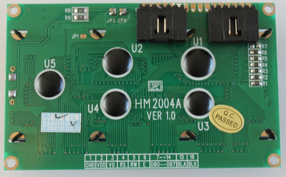
This was the first hurdle to overcome. The HD44780 standard that these character LCD displays work on states 2.7 to 5V should work fine for the logic signals, however the LCD screens incorporating these chips are a lot more restrictive: 4.8-5.2V for the logic signals. Given the conflicting information I decided to modify a PanelOne prototype board by hand and give it a go. The key is to keep the logic signals separate from the backlight voltages. The schematic is below:


The major change is the addition of the "VCC" power into pin 2 of the LCD from pin 8 of header P1. Previously this was a straight 5V, now this should be able to be either 5V or 3.3V depending on the logic of the Microprocessor we are interfacing with. I connected this up and edited the "Hello World" sketch within Arduino 1.5.7 (1.5.6 r2 works as well) to use the following pin definitions:
/*
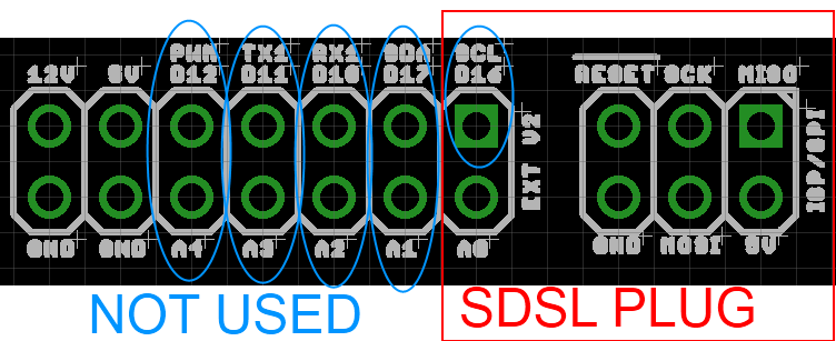
                            Arduino pin number  Duet Pin Name  Expansion header pin
 * LCD RS pin to digital pin D67                 PB16          (32)
 * LCD Enable pin to digital D23                 PA14          (10)
 * LCD D4 pin to digital pin D19                 PA10 RXD0     (14)
 * LCD D5 pin to digital pin D18                 PA11 TXD0     (13)
 * LCD D6 pin to digital pin D17                 PA12 RXD1     (12)
 * LCD D7 pin to digital pin D16                 PA13 TXD1     (11)
*/
LiquidCrystal lcd(67, 23, 19, 18, 17, 16);

Happily this worked!


I tested this with two other LCDs (old generic ones off eBay) and it worked with them as well. However as it's outside the guidelines of the LCD manufacturer's datasheets there is no guarantee that all types of HD44780 character LCDS will work in the same way.

Reading an SD card over SPI

The Duet's build in SD card supports SD2.0 and uses a 4 bit HSMCI interface. However it is often convenient to use an SD card reader mounted next to the screen, so I want to support SD over SPI which is how older 3D printer electronics and hardware interface with SD cards. The Arduino environment has a simple SPI SD library that worked straight away. The only customisation required is to make sure SD.Begin() uses the correct CS pin:

SD.begin(77);

For this example I used the SPI0_NPCS0 pin which is arduino digital pin 77. I combined the listfiles example sketch with the LCD display to list the first 4 files on a SD card:


The code (an adaptation of the listfiles example sketch):


#include <SPI.h>
#include <SD.h>
#include <LiquidCrystal.h>

File root;
// initialize the library with the numbers of the interface pins

LiquidCrystal lcd(67, 23, 19, 18, 17, 16); //RS,E,D4,D5,D6,D7

void setup()
{
  lcd.begin(20, 4);
  lcd.print("Reading Files...");
  delay(2000); //delay or else the message will not be displayed

  if (!SD.begin(77)) {
    lcd.clear();
    lcd.print("initialization");
    lcd.setCursor(0,1);
    lcd.print("failed!");
    return;
  }
   lcd.clear();
   lcd.print("initialization done");
   delay(2000); //delay or else the message will not be displayed
   lcd.clear();
   lcd.print("listing 4 files");
   delay(2000); //delay or else the message will not be displayed
   root = SD.open("/");
   lcd.clear();
   printDirectory(root, 0);
}

void printDirectory(File dir, int numTabs) {
  int row=0;
   while(true) {
     if(row>3) return;
     lcd.setCursor(0,row);
     File entry =  dir.openNextFile();
     if (! entry) {// no more files
       break;
     }
     for (uint8_t i=0; i<numTabs; i++) {
       lcd.print(' ');
     }
     lcd.print(entry.name());
     if (entry.isDirectory()) {
       lcd.print("/");
       printDirectory(entry, numTabs+1);
       row++;
     } else {
       // files have sizes, directories do not
       lcd.print("  ");
       lcd.print(entry.size(), DEC);
       row++;
     }
     entry.close();
   }

}

This sketch, and the adapted Kicad schematic are all on the Think3dPrint3d github.

Next...

I will test more LCD screens and hopefully will be able to get the next batch of PanelOnes compatible with both 3.3V and 5V.

The big job will be to port and adapt the Marlin menu system to RepRap Firmware. If anyone wants to assist with this project then drop me a line and I may be able to help with some hardware (duet board + LCD screen).

Monday, 30 December 2013

Duet FET, PSU and Stepper Driver Testing

This blog post is primarily a cut and paste from notes made during the testing of the Duet v0.3 (note the current version is 0.6). I have uploaded the design files for version 0.3 onto the archive area of the github project so the differences between the design tested in these pictures and the current design can be seen.

Normally I would try and get more detail into the post about the design decisions but that will have to wait until a later post.

FETs Testing


FETs are on by default when 3.3V regulator is disconnected as Vgs = 5V (same as when MCU turns FETs on), so software not required. (Note this setup has been replaced in version 0.6 with FETs off by default).

Tested with 10A load gives Vds = 32mV - therefore dissipating 0.32W


32mV at 10A = 3.2mOhm on resistance. As expected from datasheet.Temp measured at ~40C with thermal camera (ambient ~23C):


Track adjacent to FET (carrying input power) got marginally hotter, though nothing to worry about particularly but aim to increase track width on Duet v0.4.

A 20A load would give 1.28W dissipation. i.e. 4 times as much as 10A, therefore expect 50-60C temp rise on FET from ambient. FET rated to 175C.

PSU Testing

Perfectly happy at low loads (<750mA) (note the Arduino Due Power supply only dives a total of 800mA). 12-24V in, 4.98V out. Voltage ripple = ~30mVpk-pk (DC-20MHZ) See scope plot below:


Marginally unstable with 1A or greater load and Vin >16V.
Voltage ripple = ~100mV (DC-20MHz). See scope plot below:


At 1A load, PWM IC temp = ~40C:


At 1.5A load, PWM IC temp = ~60C:


Further testing on 20/06/13:

Inductor L1 swapped from 22uH to 8.2uH. Tested 12V to 24V input and 0A to 1.5A output load.


12V input, 1.5A load, voltage ripple+noise = ~60mVpk-pk (DC-20MHZ) See scope plot below:


24V input, 1.5A load, voltage ripple+noise = ~90mVpk-pk (DC-20MHZ) See scope plot below:

Stepper Motor Testing

Initial testing completed using stepper.ino sketch. Timings changed to 10,000 for CW and 25,000 for CCW steps. An unloaded motor was run for 30mins with these step rates and then a thermal image was taken of Duet board. See below:


The three hot-spots seen in the image are the 3.3V regulator, the MCU and the stepper driver IC. All three showing temps of around 45C.

Note: Other random colourful spots are reflections off shiny surfaces - e.g. button switches and SD card slot. 

Afterward

The main point of posting this now is to inform the discussion on the RepRap forums about potential improvements to the Powersupply:

http://forums.reprap.org/read.php?340,285306

A great example of the benefits of releasing an open source design - really high quality feedback!


Friday, 20 July 2012

Panelolu Circuit Board

Panelolu Circuit Board

Update: The Panelolu2 has replaced the Panelolu. It is much quicker to install, has adapter boards to no messing with cables and uses less pins. The blog post with the information is here, it is available to buy in our webshop.

Thanks to Jason Thompson we now have circuit boards for the Panelolu to replace the breadboards. The circuit has not changed so if you are sourcing the bits yourself the breadboard is still a good option and will work fine; however the circuit board makes assembly easier and quicker - thanks Jason!


We have assembled some boards and soldered the headers onto LCDs so there is now an option to buy the kit from us with pre-soldered components.


They are available from eMakershop and eBay, as options.

Update: The Original design by Jason Thompson is available on the Think3dPrint3d Github:
https://github.com/T3P3/Panelolu1

Friday, 29 June 2012

Panelolu - In Depth

Update: The Panelolu2 has replaced the Panelolu. It is much quicker to install, has adapter boards to no messing with cables and uses less pins. The blog post with the information is here, it is available to buy in our webshop.


Panelolu is an LCD and rotary encoder with a click button control solution which derives from the PanelMax Prusa by tommyc. It allows control of a 3D printer running Marlin firmware and Sanguinololu or similar electronics directly without having to have a computer connected. Stand-out features are the ability to start and stop prints, control print speed while printing and change many calibration settings - saving these to the memory on the ATmega 1284 (EEPROM) so they are persistent if you turn the printer on and off. Continuing with tommyc's design the panelolu has mounting brackets for the Prusa mendel or other threaded rod based printers. The brackets are separate from the enclosure so they can simply be replaced with a different design for a different mounting solution.


The Panelolu is designed to use as little soldering as possible (if the breadboard comes pre-assembled and the LCD with plugs fitted then no soldering is required at all) and to allow an easy upgrade path. It uses the SDSL card reader, so if you already have one there is no need to get another. Rather than soldering wires directly to the LCD, headers have been fitted so future changes can re-use the LCD simply.

Whats in the case
 What's in the case

The schematic is a little tangled but each wire can be traced from the Sanguinololu - through the 24 way IDC connector and ribbon cable to its final destination in the enclosure. A 22 way IDC connector would have worked fine but they're are hard to find so we use a 24 way and don't plug in pins 23 and 24.


Assembly instructions

Step 1 - Assemble the tools and components

The Panelolu can be assembled with a few basic tools:
  • Allen Key for the M3 socket head fastenings
  • Cross head screw driver for the SDSL and breadboard mounting screws
  • Small needle nose pliers for crimping connectors
  • wire cutters
If you are assembling the breadboard you will also need a soldering iron and solder.

The enclosure is on thingiverse, as a OpenScad file and STL.

The components are as in the picture below:


The rotary encoder is this one, the reset switch and pots are very generic. Most LCD panels come with mounting holes for M2.5 screws, but I prefer to drill these out slightly and use M3, the enclosure has M3 holes but they should work ok with M2.5 if you prefer to use that.

Step 2 - Assemble the breadboard and the LCD connectors.
(if you get them pre-assembled ignore this step and move to step 3!).

UPDATE: We now supply Panelolu kits with circuit boards - the breadboard instructions below are only necessary if you want to source your own components.

Note these instructions are for a the breadboard assembled with the click encoder on the right of the panel as you look at it from the front - If you want it on the left then mirror the layout.


The schematic contains the circuit diagram for the breadboard. It is laid out to minimise the number of jumper wires required - many of the connections can be bridged.


An absolute minimum of 4 rows and 29 columns are needed in order to fit the screw holes in. The components are placed as shown:


and from underneath:


As shown on the left of the picture of the underside the encoder's mounting legs have been bent round to hold it securely to the board.

The picture below shows the different circuits.

To start with make the direct connections for "ENC 1", "CONT", "BRT" and "RST".

Next use small lengths of wire to make the remaining connections. Leave as little excess wire as you are comfortable with, as it will be easier to fit into the housing:
Solid lines are wire, dotted lines solder connections.


Now do the LCD: Solder the 6 way right angle headers onto the LCD pins 1-6 and 11-16. The picture shows shrouded headers but normal right-angle pin headers are fine.

 
Step 3 - Fit the SDSL and 24 way IDC sockets

Using the cable numbering from the cable picture, you are connecting wires number 13-22 into the SDSL plug. Note the polarity as shown in the pictures. Ensure you leave at least 10 cm of length on the cable past the plug, as this will make wiring the remaining connections easier.


The easiest way to fit IDC connectors without a proper (and expensive) tool is to use a small vice. Ensure the cable is in square in the connector and the the pressure applied by the vice is even - don’t rush this bit! The back should click into the connector.


The 24 way IDC socket is fitted in the same way; ensure you use pins 1-22 of the socket (a 22 way socket would be even better but hard to find)


Step 4 - Fitting the crimp connectors.
There are three 6-way connectors and a 2 way connector that use crimp terminals. These can be crimped using small needle nose pliers if you don't have a crimping tool. Nophead has an excellent video on how to crimp them.

I found it easiest to identify the wires for each connector from the circuit diagram and the photo below and cut them to length before fitting the pins. Be sure not to make them too short!


The 12V and ground pins on the expansion header are not used by Panelolu but I have left the wires so they can be connected to something else if required. The pieces of wire offcuts in the picture are used to make the connections between the various sockets (as shown in thicker green wires in the schematic near the top of the blog post). Leave these a little longer than the minimum distance to assist with assembly at the end. On some pins you will need to connect two wires to one pin:


Once complete the assembled cable should look like this:


Step 5 - Assemble

It is easiest to first screw on the SDSL socket  and the bread board with the LCD in position, then the strain relief and finally bring the two halves together to plug in the 4 connectors. Although the SDSL itself can be fitted once completely assembled it's easier to fit it at this stage ensuring the orientation is correct.

Close it all up, being careful not to trap any wires. The length of socket setscrews used will depend on the mounting solution. There is a 5th small screw to hold the bottom of the case below the click encoder closed.
I will do a second post about mounting once I have some better pictures of it mounted on a prusa and my Mendel 90 mounting solution sorted.

Firmware

In order to use this you need a 1284P in your Sanguinololu and the Marlin firmware needs the changes that I mentioned in my previous post and have pasted here as well:
Configuration.h
Line 34:
  #define MOTHERBOARD 62 
Line 190-205:
  #define EEPROM_SETTINGS
    //to disable EEPROM Serial.....
    // please keep turned on if you can.
  #define EEPROM_CHITCHAT

  //LCD and SD support
  //#define ULTRA_LCD  //general lcd support, also 16x2
  //#define SDSUPPORT // Enable SD Card Support in Hardware Console

  #define ULTIPANEL
  #ifdef ULTIPANEL
    #define NEWPANEL  //enable this if you have a clicencoder panel
    #define SDSUPPORT
    #define ULTRA_LCD
    #define LCD_WIDTH 20
    #define LCD_HEIGHT 4

Configuration_adv.h
Line 163:
  //#define SDCARDDETECTINVERTED

pins.h, making sure to be within the sanguinololu pin definition part of the file. For my pins.h this was lines 557 - 657. I added the following 34 lines, copied from the RAMPS section of the pins.h

  #ifdef ULTRA_LCD
    #ifdef NEWPANEL
      //we have no buzzer installed
      #define BEEPER -1
      //LCD Pins
      #define LCD_PINS_RS        4
      #define LCD_PINS_ENABLE    17
      #define LCD_PINS_D4        30
      #define LCD_PINS_D5        29
      #define LCD_PINS_D6        28
      #define LCD_PINS_D7        27

      //The encoder and click button
      #define BTN_EN1 11  //must be a hardware interrupt pin
      #define BTN_EN2 10 //must be hardware interrupt pin
      #define BTN_ENC 16  //the switch
      //not connected to a pin
      #define SDCARDDETECT -1
     
      //from the same bit in the RAMPS Newpanel define
      //encoder rotation values
      #define encrot0 0
      #define encrot1 2
      #define encrot2 3
      #define encrot3 1
     
      #define BLEN_C 2
      #define BLEN_B 1
      #define BLEN_A 0
     
    #endif //Newpanel
  #endif //Ultipanel
 
Finally..
Complete kits (less the printed parts) are now available on eMaker and eBay.

Monday, 25 June 2012

Panelolu - an LCD display and control solution for Sanguinololu


As I mentioned in my previous post there is just enough space on the expansion header of the Sanguinololu for a derivative of the excellent PanelMax by tommyc. Tentatively named the “Panelolu” (which sounds like a sort of exotic icecream?), it adds brightness and contrast pots for the LCD and a minimises the reset switch on the front panel. I have adapted the PanelMax Prusa enclosure  and put it as a derivative on Thingiverse - http://www.thingiverse.com/thing:25617. Currently the design is limited for a mounting solution for Prusa and other rod-frame based printers but alternative mounting solutions for other printers will be easy to add - I am working on a Mendel 90 version right now.

  A quick video of the SluloPanel in use on my Mendel90: 


Picture of the assembled unit:

(As you can see from the printed enclosure I am still calibrating my new Mendel90 and struggling with hotends - more of this in another post)

Build instructions will be up soon and we will be supplying kits through eMakershop and ebay once we have put them together. You will need an ATMEGA 1284P, and Marlin firmware with the updates I described in my previous post for this to work. The wiring diagram and STLs for the right handed version are on Thingiverse, I will upload the SCAD and left handed STLs as soon as I have cleaned up the SCAD script - it needs some documentation!

Off to take some pictures of the assembly process and write the build instructions.
Update - more detailed post including build instructions here.

Saturday, 2 June 2012

Sanguinololu, LCD and rotary encoder with switch


Having seen the PanelMax LCD and Encoder for RAMPS, I wanted to get a similar setup working on Sanguinololu. the first step was to get an ATmega 1284P working and load Marlin firmware which supports this sort of setup with minimal changes.

Wiring and Testing


I intended to keep using the SDSL card reader (not much point in having a screen if you have to have you computer plugged in) which left very few pins unused on the microprocessor. Conveniently these are all together on the expansion header:

The image is grabbed from the .brd eagle file - easier to show than on an actual board. There are 9 I/O pins free, one of which is within the SDSL plug footprint but is not used by SDSL. Matching them up to the requirements for a standard 20x4 LCD with a HD47780 interface, and a rotary encoder (with a built in switch) gave;

For the LCD;
RS               "PWM"               Digital pin 4
ENABLE      "SDA"                Digital Pin 17
D4                "A1"                  Digital Pin 30
D5                "A2"                  Digital Pin 29
D6                "A3"                  Digital Pin 28
D7                "A4"                  Digital Pin 27
For the Encoder;
EN1              "RX1"               Digital Pin 10  (must be a hardware interrupt pin)
EN2              "TX1"                Digital Pin 11 (must be hardware interrupt pin)
SW1             "SCL"                Digital Pin 16 (Click switch)

Adds up to 9, just enough!


I connected the circuit up (quickly, I was impatient!) as shown in the Schematic. Note that the connection marked SCL on the Sanguinololu expansion header is plugged onto by the SDSL plug, but not used by the SDSL, I have connected onto this pin where it comes out of the plug as it is needed for the push switch in the encoder. The two variable resistors as 5K as that is what I had to hand, the one for the LCD brightness (R1) is set to around 1K, the one for the LCD contrast (R2) is set to around 4.5K Ohms.

After connecting it up I loaded  the Arduino 0023 IDE, and modified the "Hello world" example program from the LiquidCrystal library. The only modifications made were to the pin assignments;

    LiquidCrystal lcd(4, 17, 30, 29, 28, 27);


and define it as a 20x4 LCD

  lcd.begin(20, 4);


 So first step accomplished: the Sanguinololu talking to an LCD Screen.

Next I messed around with some of the examples shown on the Arduino rotary encoder page and ended up with a bit of a hybrid one that allows you to move the cursor around the screen with the encoder, with an arrow to show which way its going. Clicking the switch on the encoder resets it to the middle.


Left
Right

The code is available here (EncTest.pde), if you want to have a play with it.

Working with Marlin

Using the modifications on tommyc's blog as a starting point I checked and modified the Marlin Configuration.h, Configuration_adv.h and pins.h as shown below:

Configuration.h
Line 34:
  #define MOTHERBOARD 62 
Line 190-205:
  #define EEPROM_SETTINGS
    //to disable EEPROM Serial.....
    // please keep turned on if you can.
  #define EEPROM_CHITCHAT

  //LCD and SD support
  //#define ULTRA_LCD  //general lcd support, also 16x2
  //#define SDSUPPORT // Enable SD Card Support in Hardware Console

  #define ULTIPANEL
  #ifdef ULTIPANEL
    #define NEWPANEL  //enable this if you have a clicencoder panel
    #define SDSUPPORT
    #define ULTRA_LCD
    #define LCD_WIDTH 20
    #define LCD_HEIGHT 4

Configuration_adv.h
Line 163:
  //#define SDCARDDETECTINVERTED
pins.h, making sure to be within the sanguinololu pin definition part of the file. For my pins.h this was lines 557 - 657. I added the following 34 lines, copied from the RAMPS section of the pins.h

  #ifdef ULTRA_LCD
    #ifdef NEWPANEL
      //we have no buzzer installed
      #define BEEPER -1
      //LCD Pins
      #define LCD_PINS_RS        4
      #define LCD_PINS_ENABLE    17
      #define LCD_PINS_D4        30
      #define LCD_PINS_D5        29
      #define LCD_PINS_D6        28
      #define LCD_PINS_D7        27

      //The encoder and click button
      #define BTN_EN1 10  //must be a hardware interrupt pin
      #define BTN_EN2 11 //must be hardware interrupt pin
      #define BTN_ENC 16  //the switch
      //not connected to a pin
      #define SDCARDDETECT -1
     
      //from the same bit in the RAMPS Newpanel define
      //encoder rotation values
      #define encrot0 0
      #define encrot1 2
      #define encrot2 3
      #define encrot3 1
     
      #define BLEN_C 2
      #define BLEN_B 1
      #define BLEN_A 0
     
    #endif //Newpanel
  #endif //Ultipanel


Once these changes had been made, Marlin compiled to be 80k+ so definitely too big to go on the 644P. After upload the Printer status display came up:


 And rotary encoder worked fine to navigate the menu system...


I selected a random GCODE file from the SD card and started printing it (or rather the Sanguinololu controller started processing the GCODE, its not connected to anything other than a 5k pot to simulate the hotend thermistor)


Once the printing starts you can use the encoder to "tune" the speed of the printer, its currently set to 200% below:


The pseudo print continued without issues. The next step will be to tidy up the wiring and get it connected up to a live printer!