The PanelOne LCD display and control panel was originally designed for RAMPS1.4, and that is still the most sensible way to use it as it uses two 2x5 IDC cables that are readily available. The PanelOne circuit board is designed to work with 3.3V and 5V electronics and this weekend I tested it with Sanguinololu (effectively going full circle back to the original Panelolu - just a lot easier to put together and use!)
This works fine, although you do need to be careful to plug the pins in correctly:
The correct pins for Sanguinololu are:
Wire number PanelOne Sanguinololu
Aux2
1 5V 5V
2 GND GND
3 EN B Rx1
4 EN A Tx1
5 LCD DB7 A4
6 LCD RS PWM
7 LCD DB6 A3
8 LCD E SDA
9 LCD DB5 A2
10 LCD DB4 A1
Aux3
1 Not Connected
2 Not Connected
3 CS A0
4 CLK SCK
5 DO MOSI
6 DI MISO
7 EN SW SCL
8 VCC 5V
9 Not Connected
10 Not Connected
This blog post has a good image of the location of each pin on the Sanguinololu, re-posted below:
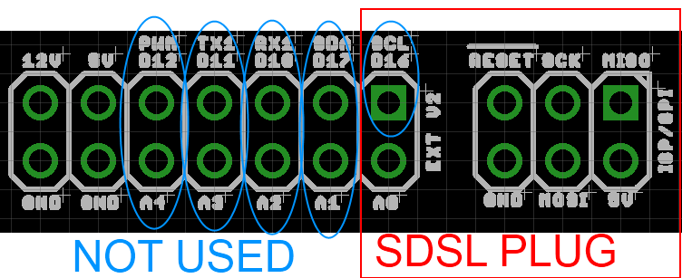
The IDC cables are numbered with wire 1 being the red coloured wire.
This will work out the box with the T3P3 version of Marlin by enabling #SDSUPPORT and #ULTIMAKERCONTROLLER in configuration.h
The process followed can be adapted to use the PanelOne on any electronics that runs Marlin and has enough free pins. Do let me know if you get it working on another board!
This is the archive blog for Think3dPrint3d, please see Duet3d.com for up-to-date information
Showing posts with label Arduino. Show all posts
Monday, 20 October 2014
Friday, 22 August 2014
Arduino based IDC cable tester
We use IDC terminated ribbon cables for the PanelOne LCD controller that we use in our Mini Kossel 3D Printer kits. Its a slow process to test these cables by confirming that the LCD, SD card, encoder etc all work so I looked for an IDC ribbon cable tester. I found a few online but they ran to ridiculous prices (~£250+) so decided to make one using an Arduino Mega and some strip board:
The circuit schematic includes the connections for a PanelOne as I had a prototype board that was no longer being used, however any 20x4 LCD screen and push switch would work.
It uses the internal pullup resistors on the arduino pins so no external components are required other than the connecting wires and headers.
I wrote a simple Arduino sketch to check the cable and display the results. It finds open and crossed wires:
The next step will be to make a circuit tester for the 50 way Duet-Duex4 expansion header cables however that would require 100 pins which is more than is available on the Mega.... I2C port expanders here we come! Also I think a PCB will be required as 100 wires on stripboard would take far too long.
As usual its all open hardware and software - available on the Think3dPrint3d Github.
I hope someone finds this useful and I would be interested to see if anyone else tries this!
As can be seen there has been no time wasted on making it look pretty, in fact it is probably the ugliest circuit I have made, ever, however it works and tests cables!
![]() |
| Stripboard IDC cable tester circuit - hot glue used to protect questionable soldering |
It uses the internal pullup resistors on the arduino pins so no external components are required other than the connecting wires and headers.
I wrote a simple Arduino sketch to check the cable and display the results. It finds open and crossed wires:
![]() |
| Arduino Circuit Tester - Start Screen |
![]() |
| Arduino Circuit Tester - Open Circuit |
![]() |
| Arduino Circuit Tester - Crossed wires (plug on backwards) |
![]() |
| Arduino Circuit Tester - Good cable |
As usual its all open hardware and software - available on the Think3dPrint3d Github.
I hope someone finds this useful and I would be interested to see if anyone else tries this!
Labels:
Arduino,
LCD Screen,
Mega 2560,
Open Hardware,
PanelOne,
Research
Subscribe to:
Posts (Atom)


