Showing posts with label 3d Printer Kit. Show all posts

Sunday, 1 June 2014

Kossel Mini and More


Our Mini Kossel is a version of the excellent Kossel delta robot printer from Johann Rocholl, the designer of the original Rostock delta. It's very quick and easy to put together and relatively economical to source parts for. We have designed some additional parts and incorporated a number of variations from around the community. The changes we have made are described below and all the additional source files are available on Github (look in the T3P3 additions directory)

The Mini Kossel can be bought as a kit or assembled from www.think3dprint3d.com  There are 5 colours in stock or we will print you a set in any custom colour we can source and print. All our parts are printed in ABS on our Mendel90 Lasercut production printers which continue to churn out excellent-quality parts every day after almost a year in service.


Linear Rails v Rollers


The initial Kossel design used linear rails


Picture (c) hiwin.com
These are great but add significantly to the cost. Using rollers on the aluminium extrusions themselves has been suggested in a number of places:

http://www.electronhacks.com/2013/12/kossel-mini-3d-printer-vertical-movement-tutorial/

http://www.thingiverse.com/thing:308369

and this comparison here: http://www.builda3dprinter.eu/rails-wheels/.

These convinced us to try the roller based option. As we are using Mitsumi aluminium extrusions we got Delrin rollers precision machined:


After many hundred of hours printing the bearings and extrusions are not showing visible wear. The only lubrication we have used is a spray of light oil containing PTFE (for example GT85). It is very simple to tighten the adjusting capscrew to adjust the pre-load and take up any slack if they do wear.

Johann is looking into using recirculating Delrin balls directly on the extrusion as well - well worth following up as and when time permits. Delrin balls are quite pricey, though, but it would be awesome if Airsoft BB pellets turned out to work well. The best carriage for these turned out to be Haydn Huntley's.


RepRapPro mini extruder


This extruder has been proven over many thousands of hours, both on RepRapPro's Mendel and Huxley printers and on our Mendel90 Lasercut multi extruder machine.


We modified this slightly to use easily obtainable pushfit bowden fittings and made a our own version of the quick and simple zip tie mount to fit to the extrusion:


Power and electronics mountings

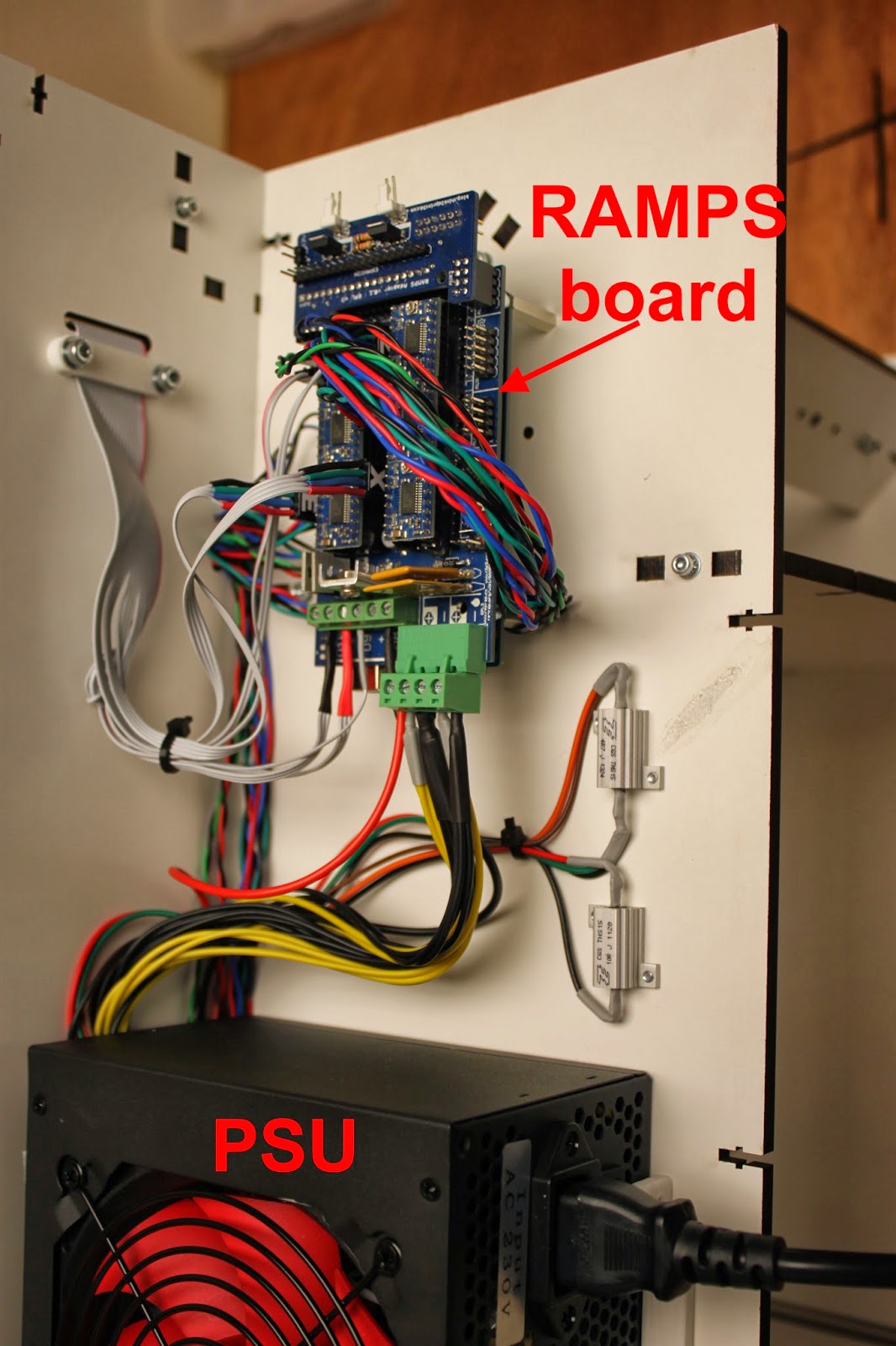
To keep the kit as simple and user friendly as possible we designed a USB and power plug plate:


That provides a neat interface with the RAMPS in the base of the printer. The non-heated bed version uses a single 5 amp laptop style power supply. We are investigating options for the heated bed version but one being considered is an extension of this plate with another plug for a heated bed power supply. The RAMPS is mounted on another simple plate:


The picture also shows some simple tabs to keep a round glass mirror plate fixed securely using M3 penny washers.


Filament management

A reel holder and filament guide complete the kit:


Build Manual

We have written a comprehensive Kossel Mini Assembly Manual for the kit which we hope will become a useful resource for all. We would really welcome feedback on the manual and suggestions for additional information to add. 

Prints

One of the Mini Kossel beta testers did these prints of the EggO egg "thrones" by mageli which are awesome. 


PanelOne LCD

Following on from the case design tutorial in SCAD here is more information of the PanelOne, a simple LCD controller for RAMPS. It is optimised for those who want to rout/etch a single sided PCB with only through-hole components. It also uses widely-available 10-way IDC ribbon cables.


The more fiddly elements of the SD card socket and logic level converter are left to an optional, and generally available, daughter board such as this one from adafruit:


image from adafruit.com
or this one:
image from hobbytonics.co.uk

The circuit board itself is designed in KiCAD as a single sided board, and was originally designed for Sumpod who commissioned us to design a board that could be routed on a PCB mill and fitted the dimensions of their printer enclosure.


In keeping with the simplicity of the design there is no adaptor board required at the RAMPS end as the pinouts are arranged to match with the AUX2 and AUX3 headers.


The complete KiCad files for the PanelOne are available on github.

Coming Soon

Watch this space... we are working on adding a heated bed and an interesting twist on multiple extruders!

Monday, 21 October 2013

Mendel90 Lasercut - Calibration

Following on from my last post which gave an overview of the Lasercut Mendel90, this post outlines the steps to take to commission and calibrate the printer.

Fortunately, as the laser cutting process standardises the frame there are only a few steps to get up and running.

Software


The Mendel90 Lasercut is not tied to a specific set of software and there are many great software packages out there for preparing 3D models for printing, for controlling the printer itself, and even for the firmware that runs on the electronics. The software covered here is what we have tested the most and recommend. The generation of the 3D models to print is outside of the scope of this post; a good place to start is Thingiverse which has many free models to download.

Slicing software

Slic3r takes a 3D model file as input and generates the "G Code" that instructs the printer. It is free and open source software that is constantly being improved and is available in versions for Windows,  Linux and Mac OSX.  Using this example of a herringbone gear set, the 3D model in "stl" format looks like this:


Slic3r allows you to set how you want the object printed, for example, you should set the layer thickness, density of infill, speed etc.


It produces text based instructions that look like this (a small excerpt from a file):
....
G1 Z0.250 F7800.000
G1 X60.415 Y89.757
G1 F1800.000 E1.00000
G1 X100.085 Y67.787 F1260.000 E11.03416
G1 X100.585 Y67.567 E11.15503
G1 X101.105 Y67.397 E11.27608
....
The G Code is simply a list of instructions which the printer follows one by one. There are many codes - the list on the RepRap Wiki is pretty comprehensive, but to get started you don't need to know this in detail as Slic3r handles it all automatically. 

We distribute a profile for Slic3r with the M90LC kit that allows you to get up and running quickly and the Slic3r manual is comprehensive.

Printer Control Software

The printer does not need a PC to run, as it can be controlled directly from the Panelolu2. However it is quicker and easier to control the printer with a PC for the initial calibration. To do this we use Pronterface which is part of Printrun. This is also available for Windows, Linux and Mac OSX.


Pronterface allows you to directly control the printer, move the axes, set the bed and extruder temperatures and load files to print. A nice feature is that it will render the G-code of a loaded file so it can be examined before printing. The screen capture below shows a slice through the herringbone gear G code


Firmware

The RAMPS controller board on the printer runs Marlin firmware, which takes the incoming G-code from a connected computer or the SD card on the Panelolu2 and acts on it. In order for Marlin to function correctly it needs to be configured with the information about the printer it is controlling. We supply a version of Marlin with all these configuration changes made and only two parameters need to be tweaked during calibration. For an overview of the basic configuration changes possible, see this blog post.

The Arduino software environment is used to upload the firmware to the board. Firmware is updated once during calibration and then should not need further configuration unless you want to take advantage of new features in future firmware or modify your printer.

Commissioning

Before calibration a number of simple tests are run to ensure everything is hooked up right.

Communication in Pronterface: on connection the following should be displayed:
Connecting..
start
Printer is now online.
Marlin 1.0.0
echo: Last Updated: Oct  8 2013 08:22:09 | Author: (T3P3, M90LC v1.0)
Compiled: Oct  8 2013
echo: Free Memory: 4340  PlannerBufferBytes: 1232
echo:Hardcoded Default Settings Loaded<
echo:Steps per unit:
echo:  M92 X80.00 Y80.00 Z4000.00 E520.00
echo:Maximum feedrates (mm/s):
echo:  M203 X300.00 Y300.00 Z3.20 E45.00
echo:Maximum Acceleration (mm/s2):
echo:  M201 X1000 Y1000 Z10 E45
echo:Acceleration: S=acceleration, T=retract acceleration
echo:  M204 S1000.00 T3000.00
echo:Advanced variables: S=Min feedrate (mm/s), T=Min travel feedrate (mm/s), B=minimum segment time (ms), X=maximum XY jerk (mm/s),  Z=maximum Z jerk (mm/s),  E=maximum E jerk (mm/s)
echo:  M205 S0.00 T0.00 B20000 X20.00 Z0.40 E5.00
echo:Home offset (mm):
echo:  M206 X0.00 Y0.00 Z0.00
echo:PID settings:
echo:   M301 P38.60 I4.55 D81.79
echo:SD init fail

Reading through this list you will see that it tells you what most of your Marlin configuration.h settings are.

The axes are then checked to ensure they trigger the limit switches, move in the right direction when commanded and that the Z axis limit switch is not too high. The extruder and bed are heated up. Once its all confirmed to work as expected the next step is calibration.

Calibration - Step 1


First the X and Y axis are set so that the extruder is the same distance above the print bed at every point. This is made simpler by using 3 point mounting for the bed and by leveling the X axis on the Z rods.


Using a sheet of paper as a feeler gauge, the distance between the extruder and the bed is set to be equal at X min and X max by moving the X-ends up and down the Z rods (blue arrow in the picture above.

Once the X axis is parallel to the bed, the single screw at the front of the printbed is used to move the bed up and down at the front until the bed is level in the Y direction. Once the bed is completely level the Z height is set. This is measured from the extruder at the centre of the bed up to the Z endstop and this number is entered into firmware.

Calibration - Step 2


Next the extruder step (E-steps) setting is checked to confirm it pushes the right amount of filament through. The E-steps are influenced by the filament type, and the hobbed bolt diameter. We set the firmware up for the hobbed bolts and filament we supply so only minor tweaking should be needed.

Using a ruler or calipers a length of filament (30mm to start) is measured off upwards from the top of the extruder. The extruder is then moved in Pronterface by that amount and if there is any difference the extruder steps per mm is recalculated to correct for the difference. The new extruder steps is then entered into the Marlin firmware.

Thats it! - time for a test print:


The fan has been left off up to this point to make calibration easier - it is now time to fit it.

Most people are opting for the acrylic cabinet which can also be fitted at this stage and goes together in a similar fashion to the frame with M3 screws and square nuts. Fitting it does not disturb the printer calibration:


The entire assembly and calibration process is described in more detail in the manual supplied with the printer kits.

I hope that helps to show what goes into the setup and calibration of the printer following assembly.

Monday, 7 October 2013

Mendel90 Lasercut - Overview

Thanks for all the interest we have been getting for the new Lasercut Mendel90! This post is to give an overview for those new to 3D printers and answer questions about how easy the M90LC is to assemble. It is not designed to replace the detailed assembly instructions and user manual which are now awaiting final feedback from our beta testers before being published.


Printer Overview


The Mendel90 Lasercut is a RepRap printer: there is much more information about RepRaps in general on the wiki but in summary it is a printer which can print the plastic parts that go into its assembly along with many other interesting and useful things. To get an idea of what people are using RepRap-style printers for, a good place to look is Thingiverse. Most CAD and 3D design software can export ".stl" files which the printing software uses to generate print instructions. The printer works by laying down layers of plastic, one on top of the other, to build up an object, in a process called fused filament fabrication.

The Mendel90 lasercut has a build area of 200mm x 200mm x 200mm and comes with a single 0.4 mm extruder nozzle which can reliably print layers as thin as 0.1mm. With a smaller extruder nozzle it can reliably print as low as 0.02mm.

Looking at the printer from the front, the Mendel90 LC axis are X left and right, Y backwards and forward and Z up and down. The print head is in the 0,0,0 position when it is fully to the left (X=0), the heatbed is fully to the back (Y=0) and it is just touching the surface of the glass on the heatbed (Z=0). The "homed" or parked printhead position is at 200,200,200.


The main components of each axis are:


The frame parts are the base, portal, buttresses, back-top and extruder "sandwich" (for potential future developments) 


The electronics are mounted at the right buttress along with the power supply unit. They support the addition of other types of electronics in future upgrades.


General points

  • The printer is made up of sub-assemblies which need to be completed before each major part of the printer is assembled. The sub assemblies can, in general, be worked on in parallel if more than one person is assembling the printer, reducing the build time.
  • The printer design in regularly updated, so refer to the manual that is distributed with your printer for the most up to date instructions.
The next section will provide an overview of the assembly process

Tuesday, 24 September 2013

Mendel90 Laser Cut - Ready to Print

The Think3dPrint3d Lasercut Mendel90 is ready! After a period of extensive prototyping and beta testing the design is set, and right now multiple versions of this printer are churning out the parts for the initial run of kits.

This is our interpretation of the Mendel90 design by Nophead based around a laser cut frame. It borrows the fixing method from the Lasercut i3 design by Shane Graber and the majority of plastic parts are from the Dibond Mendel90.


A quick orientation around the printer:-

First, the laser cut frame is made from melamine-coated MDF which is much more resistant to knocks then regular MDF and doesn't require any painting or other finishing.


It is very quick to assemble with square nuts and M3 socket cap screws


The build area is 200x200x200mm 


All the wiring comes ready to plug and play in pre-assembled cables or looms so there is no crimping or soldering required at all. The printer comes with a RAMPS controller with 5 "Ice Blue" Stepsticks and the Panelolu 2 controller as standard.


The acrylic enclosure is an optional extra which keeps the heat inside the printer to reduce warp when printing with ABS. It also helps to reduce noise and adds to the professional look of the printer. It uses the same fixing method as the printer frame and can be fixed on quickly and simply without disturbing the printer or calibration.


Overall, the design removes hassle from kit assembly at every turn. The printer can be easily put together in a day, with very little calibration required as all the critical dimensions are set by the laser cut frame. 


Kits will be available shortly (Update: now available from our webstore). We have a couple of components to finish sourcing in bulk and I will do another blog post with a run-down of the assembly process. I also need to tidy up and document the source code for the plastic parts and frame. All the source will be available on our Github before the printer goes on sale.

We are supporting the RepRap stand at the TCT show this year and will have a Mendel90 LC or two on display. The TCT show is free to register for so please do come round and say hello.