As always this is Open Source Hardware so the OpenSCAD source and supporting control knob file is shared on GitHub.
The electronics to encase
The PanelOne is a simple back board for a 20x4 character LCD with a encoder, a SD card board and brightness and contrast pots. I will go into the rationale and design of it in another post.

The aim for the case is to be quick and easy to print and use the the minimum of additional screws and other fixings.
Step 1 - Measurements
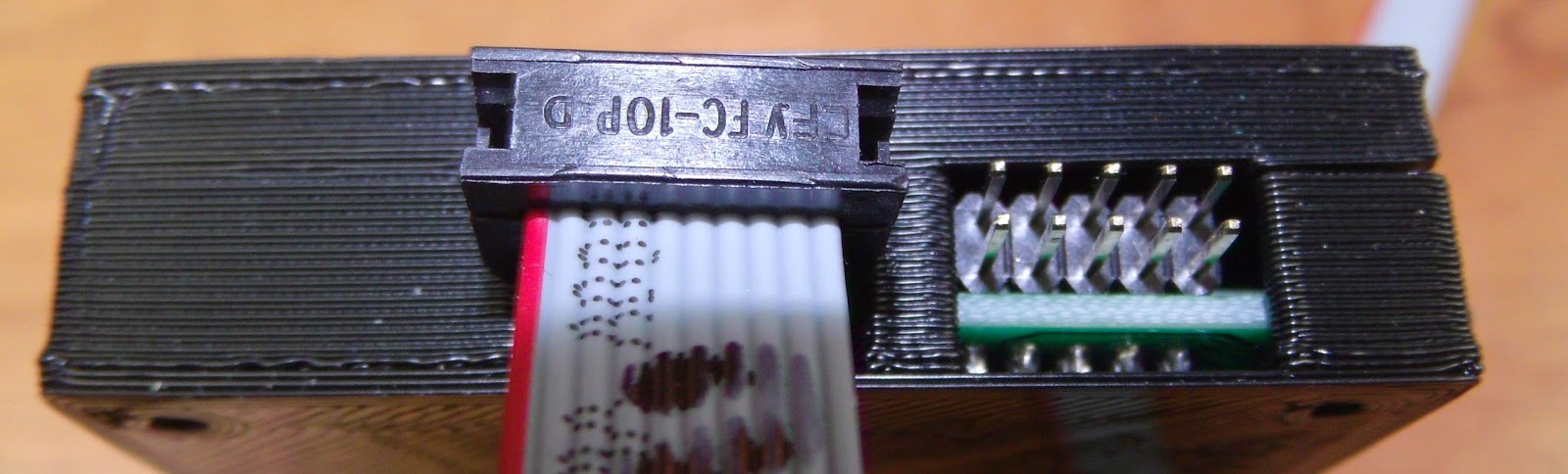
First step is to take measurements of the dimensions of the electronics - these can be taken from the CAD files if you have them:

This shows using the dimension function in KiCAD, although you can read the co-ordinates directly. The other, and my preferred, option is to take direct measurements:

This allows for the effect of the assembly processes to be taken into account easily.
Step 2 - Model the Electronics
Depending on how complex a case you are making, this step can be very simple or very complex. For a great example of how complex a circuit model model can be, check out UrielGuy's model of the Sanguinololu electronics:

In this case I am going to keep it simple.
Start by assigning the measurements to variables - you will thank yourself many times over as you come to reuse or modify these.:
clearance=0.8;
wall_width=1.6; //minimum wall width //should be a multiple of your extruded dia
layer_height=0.2;
//LCD screen
lcd_scrn_x=99;
lcd_scrn_y=40.5;
lcd_scrn_z=9.4;
lcd_board_x=99;
lcd_board_y=61;
lcd_board_z=1.6; //does not include metal tabs on base
lcd_hole_d=3.4;
lcd_hole_offset=(lcd_hole_d/2)+1;
//board edge to center of first connector hole
lcd_connect_x=10.2;
lcd_connect_y=58.4;
//PanelOne circuit board
pl_x=136;
pl_y=lcd_board_y;
pl_z=4; //excluding click Encoder and SD card and cable headers, but including the soldered bottoms of the through hole connectors
pl_mounting_hole_dia=3.4;
pl_mounting_hole_x=133.6;
pl_mounting_hole1_y=3.4; //only bothering with 2 holes at this point
pl_mounting_hole2_y=58.4;
//rotary encoder
click_encoder_x=13.2;
click_encoder_y=12.6;
click_encoder_z=6;
click_encoder_shaft_dia=6.9+clearance;
click_encoder_shaft_h=12.2;
click_encoder_knob_dia=24;
click_encoder_offset_x=112.2;
click_encoder_offset_y=30.8;
//contrast and brightness holes
cb_dia=4; //hole diameter for adjustment screw
cb_h=15;
con_offset_x=107.2;
con_offset_y=16.1;
con_offset_z=pl_z;
bri_offset_x=117.1;
bri_offset_y=16.0;
bri_offset_z=con_offset_z;
//headers
//lcd connection header
lcd_h_x=(16*2.54)+2.54;
lcd_h_y=2.54;
lcd_h_z=3; //this is the gap between the circuit board caused by the plastic spaces on 2.54mm headers
lcd_h_offset_x=lcd_connect_x;
lcd_h_offset_y=lcd_connect_y;
lcd_h_offset_z=pl_z;
//IDC headers, use the clearance required for the plug
//these are much bigger on z than the actual headers for clearance
idc_h_x=16; //not all will be within case
idc_h_y=14+clearance;
idc_h_z=pl_z+click_encoder_z;
idc1_offset_x=128.4;
idc1_offset_y=20.5-clearance/2;
idc1_offset_z=-wall_width;
idc2_offset_x=idc1_offset_x;
idc2_offset_y=39.6-clearance/2;
idc2_offset_z=idc1_offset_z;
//SD card slot
SD_slot_x=24.5+clearance; //wider for clearance
SD_slot_y=29.5;
SD_slot_z=4;
SD_slot_offset_x=100.5-clearance/2;
SD_slot_offset_y=39.5;
SD_slot_offset_z=pl_z;
//case variables
shell_split_z = pl_z+SD_slot_z; //board split in the top of the slots
shell_width=wall_width+clearance;
shell_top = pl_z+click_encoder_z+2;
Then I write a number of small functions to draw up the components:
module LCD_assembly() {
translate([0,0,lcd_h_offset_z+lcd_h_z])
lcd();
pl_board();
//lcd connection header
color("black")
translate([lcd_h_offset_x,lcd_h_offset_y,lcd_h_offset_z])
cube([lcd_h_x,lcd_h_y,lcd_h_z]);
}
//LCD screen
module lcd() {
difference(){
union(){
color("OliveDrab")
translate([0,0,0])
cube([lcd_board_x,lcd_board_y,lcd_board_z]);
color("DarkSlateGray")
translate([(lcd_board_x-lcd_scrn_x)/2,(lcd_board_y-lcd_scrn_y)/2,lcd_board_z])
cube([lcd_scrn_x,lcd_scrn_y,lcd_scrn_z]);
}
for(i=[lcd_hole_offset,lcd_board_x-lcd_hole_offset]){
for(j=[lcd_hole_offset,lcd_board_y-lcd_hole_offset]){
translate([i,j,lcd_board_z])
cylinder(r=lcd_hole_d/2,h=lcd_board_z+3,$fn=12,center=true);
}
}
}
}
//PanelOne circuit board simplified
module pl_board() {
difference(){
union(){
color("lightgreen")cube([pl_x,pl_y,pl_z]);
//click encoder
color("darkgrey"){
translate([click_encoder_offset_x,click_encoder_offset_y,pl_z+(click_encoder_z)/2])
cube([click_encoder_x,click_encoder_y,click_encoder_z],center=true);
translate([click_encoder_offset_x,click_encoder_offset_y,pl_z+click_encoder_z+(click_encoder_shaft_h)/2])
cylinder(r=click_encoder_shaft_dia/2,h=click_encoder_shaft_h,center=true);
//contrast and brightness pots
translate([con_offset_x,con_offset_y,con_offset_z+cb_h/2])
cylinder(r=cb_dia/2,h=cb_h,center=true);
translate([bri_offset_x,bri_offset_y,bri_offset_z+cb_h/2])
cylinder(r=cb_dia/2,h=cb_h,center=true);
}
}
translate([-0.1,-0.1,-0.1]){
cube([93,45,pl_z+2]);
cube([6,lcd_board_y+1,pl_z+2]);
}
//mounting holes
translate([pl_mounting_hole_x,pl_mounting_hole1_y,(pl_z+3)/2])
cylinder(r=pl_mounting_hole_dia/2,h=pl_z+3,center=true);
translate([pl_mounting_hole_x,pl_mounting_hole2_y,(pl_z+3)/2])
cylinder(r=pl_mounting_hole_dia/2,h=pl_z+3,center=true);
}
//SD board
color("lightblue")
translate([SD_slot_offset_x,SD_slot_offset_y,SD_slot_offset_z])
cube([SD_slot_x,SD_slot_y,SD_slot_z]);
//IDC headers
color("darkgrey"){
translate([idc1_offset_x,idc1_offset_y,idc1_offset_z])
cube([idc_h_x,idc_h_y,idc_h_z]);
translate([idc2_offset_x,idc2_offset_y,idc2_offset_z])
cube([idc_h_x,idc_h_y,idc_h_z]);
}
}
It is a good idea to split down the design into logical blocks - these can be reused. The LCD module is re-used from the Panelolu2 case design for example.
I used the color function within OpenSCAD to make this render easier to view:

Step 3 - The Case
The case will be a simple design with back and front halves, along with a knob for the click encoder. It will be held together with M3 screws. A mounting method will be discussed in a later post.
The back and front halves are very simple to code, since the hard work has already been done in defining the electronics which is used to "cut" the holes required in the case.
module case_screw_holes(nut_trap=false,z_height=0, dia=lcd_hole_d) {
for(i=[lcd_hole_offset,pl_mounting_hole_x])
for(j=[lcd_hole_offset,pl_mounting_hole2_y]){
if (nut_trap) {
translate([i,j,z_height])
cylinder(r=dia/2, h=shell_width*2, $fn=fn);
translate([i,j,z_height])
cylinder(r=m3_nut_diameter_bigger/2+layer_height*2, h=shell_width, $fn=6);
} else {
translate([i,j,z_height])
cylinder(r=dia/2,h=shell_width*2+30,$fn=12,center=true);
}
}
}
module back() {
difference(){
translate([-shell_width,-shell_width,-shell_width])
cube([pl_x+shell_width*2,pl_y+shell_width*2,shell_split_z+shell_width]);
translate([-clearance,-clearance,-clearance])
cube([pl_x+clearance*2,pl_y+clearance*2,shell_split_z+clearance+0.01]);
LCD_assembly();
case_screw_holes(false,-shell_width);
}
//support pillar
translate([6,6,0])
difference(){
cube([10,10,pl_z+lcd_h_z]);
translate([wall_width,wall_width,0])
cube([10-wall_width*2,10-wall_width*2,pl_z+lcd_h_z+0.1]);
}
}

module front() {
difference(){
translate([-shell_width,-shell_width,shell_split_z])
cube([pl_w+shell_width*2,pl_y+shell_width*2,shell_top-shell_split_z+shell_width]);
translate([-clearance,-clearance,shell_split_z-0.01])
cube([pl_w+clearance*2,pl_y+clearance*2,shell_top-shell_split_z+clearance]);
LCD_assembly();
case_screw_holes(false,shell_top+shell_width);
}
}


Step 4 - Tweak
The great thing with rapid prototyping is the ability to quickly test out designs and make improvements. The first rough print had a couple of issues:

support for the LCD needed
clearance for the IDC connectors needs moving up
Overall the following issues were noted:
- The holes for the IDC plugs for the cables need to be wider and higher up in the case, easiest to replace with a single cutout.
- The box spacer used as a support in the back interfered with the back of the LCD
- To hold the board more rigidly some supports are required - the corners are the easiest place for these.
Fixes:
Change the IDC header dimensions, only one "header" needed in the model now:
//these are much bigger on z than the actual headers for clearance
idc_y_x=16; //not all will be within case
idc_y_y=37.9;
idc_y_z=6.39+2.5;
idc1_offset_x=128.4;
idc1_offset_y=18.1;
idc1_offset_z=1.61;

Remove the box spacer and add supports to the front and back:
module back() {
side=8; //for the supports
difference(){
union(){
difference(){
translate([-shell_width,-shell_width,-shell_width])
cube([pl_x+shell_width*2,pl_y+shell_width*2,shell_split_z+shell_width]);
translate([-clearance,-clearance,-clearance])
cube([pl_x+clearance*2,pl_y+clearance*2,shell_split_z+clearance+0.01]);
LCD_assembly();
}
//corner supports
for(i=[-wall_width,pl_y-side+wall_width]){
translate([-wall_width,i,-shell_width])
cube([side,side,8.75]);
translate([pl_x-side+wall_width,i,-shell_width])
cube([side,side,4.35]);
}
//additional support
translate([lcd_board_x-side,-wall_width,-shell_width])
cube([side,side/2,8.75]);
}
case_screw_holes(false,0);
}
}

module front() {
side=8; //for the supports
difference(){
union(){
difference(){
translate([-shell_width,-shell_width,shell_split_z])
cube([pl_x+shell_width*2,pl_y+shell_width*2,shell_top-shell_split_z +shell_width]);
translate([-clearance,-clearance,shell_split_z-0.01])
cube([pl_x+clearance*2,pl_y+clearance*2,shell_top-shell_split_z +clearance]);
LCD_assembly();
}
//corner supports
for(i=[-wall_width,pl_x-side+wall_width])
for(j=[-wall_width,pl_y-side+wall_width]){
translate([i,j,shell_split_z])
cube([side,side,shell_top-shell_split_z+wall_width]);
}
//additional supports
for(i=[-wall_width,pl_y-side/2+wall_width]){
translate([lcd_board_x-side,i,shell_split_z])
cube([side,side/2,shell_top-shell_split_z+wall_width]);
}
}
case_screw_holes(false,shell_top+shell_width);
}
}

The final case:

Step 5 - Optional Extras
For models I use often or that go through many iterations where I want to quickly change between different parts it makes sense to simplify the selection of what part of the model to display. At the top of the scad file I have:
///////////////////////////////////////////////////////////
//front, back or Assembly
///////////////////////////////////////////////////////////
side=2; //1 = front, -1 = back 2=printing layout -2 Electronics module 0=assembly model
///////////////////////////////////////////////////////////
//front, back or Assembly
///////////////////////////////////////////////////////////
side=2; //1 = front, -1 = back 2=printing layout -2 Electronics module 0=assembly model
///////////////////////////////////////////////////////////
This then determines what is rendered using a list of if statements used because, annoyingly, OpenSCAD does not appear to support a "switch" statement.
///////////////////////////////////////////////////////////////////////////////////////
// front
if (side==1)
{
front();
}
// back
else if(side==-1)
{
back();
}
//Printing plate
else if(side==2)
{
translate([shell_width,pl_y*2+shell_width*4,shell_top+shell_width])
rotate([180,0,0])
front();
translate([shell_width,shell_width,shell_width])
back();
translate([pl_y*0.5,pl_y*1.5+shell_width*2,shell_width])
knob_assembly(click_encoder_knob_dia/2);
}
//Electronics
else if(side==-2)
{
LCD_assembly();
}
//assembly
else
{
back();
front();
LCD_assembly();
translate([click_encoder_offset_x,click_encoder_offset_y,wall_width+ click_encoder_shaft_y+click_encoder_z-2])
knob_assembly(click_encoder_knob_dia/2);
}
///////////////////////////////////////////////////////////////////////////////////////
Thus changing one number allows you pick the render you want:

That's all for now - I hope to get a blog post out about the PanelOne itself soon.


