New Duet electronics version 0.8.5
The Duet is a new 3D Printer controller board that is compatible with the Arduino Due. It has been developed by Andy Hingston and Tony Lock from Think3dPrint3d in conjunction with RepRapPro and with much advice from Chris Palmer (Nophead). This 3D Printer controller combines the Arduino Due microcontroller with 4 stepper motor controllers, Ethernet, Hi-Speed SD card slot and more.
 |
| Duet Main board |
 |
| Expansion board for up to 5 extruders in total |
Hardware Overview
The Duet runs the 32 bit, ARM core SAM3X8E microprocessor, as found on the Arduino Due. This is a step change from existing controllers using 8 bit mcroprocessors and leaves loads of overhead to do cool things (like run a webserver, run delta bots much faster etc)
 |
| Duet Connections |
3D Printer hardware control
On the main board are 4 Allegro A4982 stepper drivers (X,Y,Z,E0), 3 FETs (Heated Bed, E0, Fan), 2 Thermistor inputs (Heated Bed, E0), 4 Endstop channels (X, Y, Z, E). The stepper drive current is electronically controlled with an I2C Digital potentiometer. As an alternative to using screw terminals there are double rows of pin headers for two wiring looms, 1 for the heated bed and one for the rest of the printer. This allows for the easy use of wiring looms to simplify printer assembly.
Connectivity
The USB port is a Hi-Speed A/B type allowing for standard for USB control from a PC and potentially support for USB devices in the future. The SD card socket is fully SD 2.0 compliant, supporting faster access and cards up to 32 GB. A 10/100T Ethernet port allows for network control via an on-board web server.
Power
Power in comprises a 12-24V main input along with connections to control a standard ATX power supply. On board the Duet can use USB for 5V, incoming 5V from the ATX power supply and it has an inbuilt 2A switching power supply to provide 5V to support future expansion (for example powering a connected USB device).
Expansion board
The expansion board has a further 4 A4982 stepper drivers (E1, E2, E3, E4), another I2C digipot, 4 FETs (E1, E2, E3, E4) and corresponding thermistor inputs. It also has a header exposing 3 Serial channels, SPI bus and 2x I2C buses for further expansion.
 |
| Expansion board connections |
Open Hardware
The Duet hardware design is licensed under the CERN OHW License 1.2: the design is free to be distributed and modified within the terms of this license. All the design files are here on Github.

Not only is it Open Hardware but it was completely designed using the Open Source software package KiCAD so hacking and building on this design its accessible to all.
A detailed blog post on the hardware design will follow.
A detailed blog post on the hardware design will follow.
Software Overview
The Duet runs RepRap Firmware, a new C++ firmware by Adrian Bowyer. The firmware can be compiled with the Arduino IDE (tested with 1.5.4) or Eclipse and uploaded like other firmware, but the aim is for much of the printer specific information to be set by Gcode which is read on machine start from the SD card.
The software supports receiving GCode from 3 locations:
- Over the USB serial port (as current 3D printer controllers do) - making it compatible with software such as Pronterface and Repetier host.
- From the SD card, which also stores the web server files and the config files.
- From the Ethernet interface via the webserver:
 |
| RepRap Firmware web interface |
RepRapPro have a video here showing the web interface in use with the Ormerod printer.
The software is adding new features daily, the most recent being added alpha level support for multiple extruder printing - see the T3P3 github, RepRapFirmware, multi extruder branch.
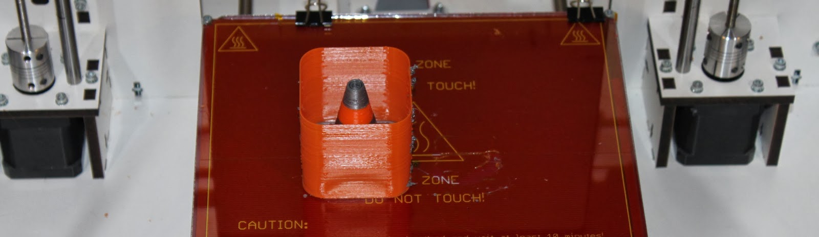
Here is a picture of the first dual extruder print from a Duet and expansion board combo. I will add a video when I have a chance to edit it!

The software is adding new features daily, the most recent being added alpha level support for multiple extruder printing - see the T3P3 github, RepRapFirmware, multi extruder branch.
Here is a picture of the first dual extruder print from a Duet and expansion board combo. I will add a video when I have a chance to edit it!
Where to get it
We will stock our Web Shop tomorrow with a limited number of the first Duet production run available for immediate purchase, with expansion boards to follow next week. A larger production run is underway so don't despair if you miss the first batch.
Update: The Duex4 Expansion boards are available on our Web Shop. The source files for the board are on Github.
Update2: Those who are in Germany or Austria can now buy the Duet and Duex4 from RepRap Austria
Update: The Duex4 Expansion boards are available on our Web Shop. The source files for the board are on Github.
Update2: Those who are in Germany or Austria can now buy the Duet and Duex4 from RepRap Austria
You've been busy,,, very nice :)
ReplyDeleteHas the firmware delta support?
ReplyDeleteNot yet....
DeleteMy fork of the firmware does now, it's at https://github.com/dc42/RepRapFirmware/tree/dev.
DeleteDavid your work is excellent.
DeleteI want to develope a firmware with polar suport.
I have knowledge with electronics, with arduino, C language and 3d printers... But I don't know how to start.
Can you help me? Just I want to know where I can start and what steps i need to do to develope something like that.
Thank you
Eduardoz as far as I can tell, you will need to edit:
DeleteMove.cpp
Move.h
Configuration.h
DriveMovement.cpp
DriveMovement.h
DDA.cpp
DDA.h
GCodes.cpp
Platform.h
Potentially make a new gcode folder for a polar printer in the SD card folder.
And then mess with some of the JS for the website part of it.
thanks,
Deletei had stopped the coding project, looking for mechanical components, but i will back on it again.
Thanks!
thanks,
Deletei had stopped the coding project, looking for mechanical components, but i will back on it again.
Thanks!
Cool board! will post over at OpenBuilds I am sure the guys will want to know about this one.
ReplyDeleteawesome board from my experience, would love to see some CNC control firmware i could throw at it as the ethernet port and web interface make this soo user friendly.
DeleteYou can control some CNC machines from it (Laser cutters and 3d printers) I don't know what additions would need to be made, if any to control Routers or higher axis machines.
DeleteCan the board be connected via wifi somehow? Ethernet cable isn't going all the way up to my attic!
ReplyDeleteHi Kester - The cheapest way is probably to use a spare/second hand wifi router to create an ethernet/wifi bridge. If you don't have an old one lying around then a ethernet-wireless bridge can be bought inexpensively.
DeleteOK, scrub that comment - just seen this will be easy to adapt:
ReplyDeletehttp://www.ebay.com/itm/New-WiFi-Express-USB-Ethernet-Wireless-Adapter-For-Tablet-PC-Smart-Phone-laptop-/141137638605
There are many different ethernet to wireless bridges on the market. I have not tried them all but that should do the trick.
DeleteMy Prusa machine has a Sanguinololu board with ATMEGA 8bit controller and Sprinter firmware. At the end of lines and complicated junctions during a print I get "polyps" or "pustules" of PLA pushed out of the side of the print. There are also ridgesat the ends of the chords on circles. This may be due to the controller running out of X,Y steps while data is being processed. Hopefully, the 32bit ARM will be much, much faster and minimise this problem.
ReplyDeleteCan you support this thesis and will ther Duet (and or/firmware) have a cache for buffering steps so as to avoid thes hiccups in xy motion?
Bill Graham
Hi Bill
DeleteI have seen the issue you describe before and I am not sure that its caused by the controller running out of XY steps. I have not used Sprinter for a long time but Marlin definitely buffers steps.
The problem sounds more like an issue that could be solved by calibration rather than caused by the speed of the electronics. I would look at your retraction settings and run some tests with various simple test objects. I would also recommend moving to a more uptodate firmware such as Marlin.
Tony
Hello,
DeleteWith Sprinter my "PLA-polyps" comes from printing directly from computer...
Prints are miracle healed when calling g-gode from SD-card. It seems that there is slight pauses for other processes with my USB...
358Eki
Eki, running from USB definitely can cause problems in some setups. Printing from an SD card is a good idea.
DeleteThat said I have seen these issues even when printing from SD so its not always the fix.
Thanks to both for these tips. I notice that the polyps occur at the start or end of a move to a new line (sometimes leaving a whisker). The defects show only with some makes of filament. I will act on your tips as advised. Thanks a lot.
DeleteBill
PS Apologies for the delay in replying. My desktop PC PSU went US.
Hi Bill
DeleteI definitely would recommend going with a more recent firmware and testing retract settings as the first point of call.
Cheers
Tony
Does no delta support mean we can't use this board to build richrap's 3DR (or at least, not yet)?
ReplyDeleteHi Kester
DeleteDelta support is a priority and I am considering using the RepRap community bounties program:
http://forums.reprap.org/list.php?337
to push this forward. At this stage through RepRap Firmware does not have delta support.
Delta printers are now supported in my fork of the firmware, see https://github.com/dc42/RepRapFirmware/tree/dev.
Deletewhere can I find the expansion board ?
ReplyDeleteHi The expansion boards are in production, we have received the first few and are testing them before putting up a listing. Either the end of this week or early next week.
Deletethank you for your reply
DeleteAs you will have noticed we are taking longer than expected. I wanted to ensure a complete testing procedure wa inplace and did not get it done by the Christmas break. I anticipate finishing this off over the weekend and listing early next week. Sorry for the delay!
Deleteplease hurry with listing those! I presume that the firmware for it is 5 extruder-capable too? That is still a problem with marlin, only 3 extruders supported (yet) and only via the clumsy 'Tn- but the E value does not change'. I'd reslly like a 4 or 5 extruder setup with simultanous independent extrusion on two motors. (yes, one can wish...)
DeleteWould the used A4982 drivers allow the use of 2,5A Nema 17 stepper motors?
ReplyDeleteHi, the drivers are rated up to 2A max - to achieve that they would need heatsinking and cooling. So to drive 2.5A through the motors would be too much. That said they could be fine if you dont want to run the motors at their maximum torque. alot of stepper motors are rated to run at 80C when they are drawing max current which is pretty hot! do you have a link to the stepper model - I can giv a better answer then.
Deletei'm having compile errors with the duet branch, even after copying the arduino libraries properly into the reprapfirmware folder. it says utility/compiler.h not found or no such directory. ive tried with arduino 1.5.4 and 1.5.5. what have i done wrong?
ReplyDeleteHey Chakalaka
DeleteAre you using the RepRapPro version of the RepRap Firmware from their github or the one from the T3P3 github?
Cheers
Tony
This comment has been removed by the author.
ReplyDeleteHey Tony, im using the RepRapPro firmware Duet branch: https://github.com/reprappro/RepRapFirmware/tree/duet
ReplyDeleteIs there any ETA for the expansion board? What are the problems with it?
ReplyDeleteHey Jelle
DeleteNo problems at all, we are testing these in house and the first large batch went to a existing pre-order. The plan this weekend is to make a rig to test them quicker so we will have enough to list. I have just published an update to the multi extruder branch of the firmware which now supports 5 extruders.
I will keep everyone informed through the blog and twitter (@think3dprint3d) once they are up for sale. Thanks for the patience.
Hey Jelle
DeleteI am looking into implementing something like M160 to do what you want. The firmware is working with 5 extruders and I will continue to add features.
The Expansion board, called the Duex4 is now available:
ReplyDeletehttp://www.think3dprint3d.com/Duex4-Duet-Expansion-Board
Hy Tony,
ReplyDeletejust finished to desing my 800x600x700mm 3d printer and need to buy a board.
1) can i connect 2 nema 17 in parallel to move the base with heated bed?
2) because of the big heated area i would like to supply the heating system with 230VAC (400W needed): can your board control an SSR? is PID the algorithm you use?
Thanks for your answers and compliments for your project!
Andrea.
Hi Andrea
DeleteWow, quite a build area!
1) we use 2 Nema17 motors for Z but you might want to look at this thread before choosing to wire in parallel :
http://forums.reprap.org/read.php?1,123038,123153
which motors do you intend to use and how much current do you need to give them to get the torque you need to move that bed? The A4982 is rated to 2A with enough cooling - if you are close to or more than that then you will need a more powerful stepper driver or you could modify the firmware to run each motor of a separate driver to share the load.
2) The bed output can control a relay - I use it that way on a couple of my printers which have high current beds. The firmware currently has the bed set to bang bang but it can be switched to PWM with PID like the hotends (which use PWM and PID). Arduino Due specifies the PWM frequency as 1K but the processor can do a whole rage of frequencies and even two different ones if required although that would require firmware modification as well. With such a big bed I guess it would have quite good thermal mass you you could find that bang bang works ok.
Cheers
Tony
Hy Tony,
Deletemany many thanks for your aswers.
for question 1 i fonud this stepper that it seems to me a compromise
http://www.omc-stepperonline.com/09deg-nema-17-bipolar-stepper-motor-2a-46ncm-17hm192004s-p-122.html
I will sure buy the expasion board, avoiding paralle/series and using another output.
I'm calculating the torque but i'm quite confident 2 nema 17 with 36.8 N/cm will be enough.
For question 2 it's perfect the on-off control. If i'll have time i'll try to update it with PID control.
Thanks for your clarification and then i'll go to buy the boards.
Regards.
Andrea.
No worries Andrea
DeleteIf 36 Ncm is enough then you could try these :)
http://www.think3dprint3d.com/Hardware/Stepper-Motor-NEMA17
Hy Tony,
ReplyDeletei saw the stepper but the other i found is 0.9° step. Do i have in your board the 12V necessary to run the motor?
Is it possible to connect an external stepper driver to drive a more powerful motor from your board?
Sorry to stress you with 100 questions but i have to be sure your board is what i'm looking for.
Thanks again for your patience!
Regards.
Andrea.
Hi Andrea
DeleteNo Stress! So the motor you linked is manufactured by the same manufacturer as the one we sell they are actually very similar the main difference being the one you chose is 0.9 deg per step and ours is 1.8 also the one you linked is slightly higher torque.
Yours is the 17hm19-2004S
http://www.osmtec.com/hybrid_stepper_motor_nema_17_hm.htm
Ours is the 17HS19-1684S
http://www.osmtec.com/nema_17_step_motor_17_hs.htm
So you will be able to run those motors but without cooling the drivers won't do the full 2A per phase. Note though that motors will be at 80C with that much current. The Duet will take 12 to 24V input and the stepper drivers limit the current to the motors.
For using more powerful stepper drivers the expansion board could easily be replaced to use different drivers. The details would depend on the external drivers required. A number of people are interested in using this to drive CNC or larger printers so it may make sense to do an expansion board to drive the heavy axes and then use the inboard steppers for the lighter axis or extruders.
Cheers
Tony
Hi Tony,
Deletemany many thanks again! Now everything is clear. I'll buy the board and expansion. Using zero backslash bearing to move extruder and y axis i should have very low friction. Also i'll have very low mass to move so i'll use the motor i mentioned. Now i know in case of need i can connect bigger drivers and change with bigger motors.
Can i fit heat sink and fan in the allegro A4982?
Thanks.
Andrea.
Hey Andrea
DeleteNo worries. Yes you can fit a heatsink - just ask when you guy the board and we can add some small ones for you to start with. If you need a fan then a cheap 12V fan can be mounted blowing on the drivers but you may find that this is not required.
Cheers
Tony
Hi Tony, about more powerful stepper motors, if i understood well the output of duet that control the stepper can be the input to an external driver to control a nema 23 or other motor. Logically the external driver is supplied with an independent power supply. Just for example can i connect the duet output to this one?
Deletehttp://www.hybrid-steppermotors.com/china-industrial_4a_stepper_motor_drivers_nema_23_57mm_2_phase_24_volt-1185027.html.
Thanks for your patience.
Regards.
Andrea.
Hi Andrea
DeleteI have not tried it but looking at the data on the page you linked the fist issue you would need to overcome is that those drivers appear to use 5V logic to drive them, the Duet works on 3.3V logic. Given the amount of power then can handle it might be prudent to isolate them in some way from the duet (eg opt isolator) which could also alow you to change the logic level at the same time.
The expansion header has many free pins so if you correctly interfaced them there is no reason why the duet could not drive these instead of the standard expansion board.
Hy Tony, can i run my duet with repetier host?
DeleteThanks.
Regards.
Andrea.
Hi Andrea
DeleteI have not tested it with Repetier host but it should work with any program that sends GCode in the standard way.
You will not yet be able to use the Repetier firmware - although the idea is under discussion here:
http://forums.reprap.org/read.php?267,316757
Cheers
Tony
Hi Tony,
Deletemany thanks for your, as always, fast answers! I take the occasion to ask you if i can use this stepper driver with the duet:
http://www.pibot.com/store/electronics/pibot-stepper-driver-board.html#.UxnnAT95PSU
I would like to use for y and z axis two nema 17 in parallel using the duet out (expansion pins?).
Many thanks again.
Andrea.
Hey Andrea
DeleteThe Duet expansion pins can drive a wide range of expansion modules - but the critical thing to ensure is that the module plugged in is happy with 3.3V logic
I had a look on the page you linked - no mention of the logic level of the pibot driver boards :/
So if the pibot stepper drivers will work with 3.3V logic then they can be controlled from the Duet - if not then they need a 3.3V-5V logic convertor in between.
Cheers
Tony
I am contemplating building a new printer using the CoreXY drive system. That has been ported to Marlin already, are you at some future time going to implement it in your Duet firmware ? The ability to handle a 4 extruder setup like the Kraken is what I want to implement with a CoreXY.
ReplyDeleteVery impressive work ! Well done.
Hey William
DeleteSince the work has already been done to implement coreXY in marlin it should be straightforward to port it. That said its going to be some time before I am able to focus on that. The code is all on github so if you want to have a go I would be happy to help where I can.
Tony
Have there been any further developments on a coreXY implementation?
DeleteI would be happy to add CoreXY support to the firmware (I recently added delta support), however I don't have a CoreXY printer to test it on.
DeleteHi
ReplyDeleteI have been using Arduino Mega 2560 and marlin firmware.
Marlin has X_MIN_ENDSTOP_INVERTING = false option.
How can I invert my axis in Duet firmware? Is there any G-code, or what is the easiest way to invert axis?
Now my axis is moving wrong direction, and also endstops is not working correct.
- Janne
Wrong option, I mean #define INVERT_X_DIR true ...
ReplyDelete-Janne
Hey Janne
DeleteWe need to add this feature to the firmware - for now you could try wiring the motor with the coils reversed as a quick fix.
Tony
This comment has been removed by the author.
ReplyDeleteHi
ReplyDeleteYes, I tried that first, but my home direction goes wrong.
I tried to reverse home direction command HOME_DIRECTION 1 -> -1...but it not work?
I'm stuck.
Hi Janne
DeleteIf you look at the more recent versions of the firmware you will see that homing is implemented as a g-code file. This allows you to specify in which direction to go (-200 or +200 for example) and to look for an endstop hit. Then you can say at what point that endstop hit is (for example +190).
If you are using my Multiextruder banch check here:
https://github.com/T3P3/RepRapFirmware/tree/Multi_Extruder_Test/SD-image/sys
else for the RepRapPro version check
https://github.com/reprappro/RepRapFirmware/tree/duet/SD-image/sys
Cheers
Tony
Okey, Thanks.
ReplyDeleteI need to test it.
-Janne
There is a working firmware for delta printer?
ReplyDeleteHi, the firmware does not yet support delta printers. Its on the todo list but we have not yet started working on it.
DeleteCheers
Tony
There is now, it'a at https://github.com/dc42/RepRapFirmware/tree/dev.
DeleteWill it have support for a LCD?
ReplyDeleteAdding support for the lcds is on the list but I want to work on a couple of other things first
DeleteHi!
ReplyDeleteI always wanted to try printing things on my big cnc router :)
Proplem is:
The cnc mill needs 4 Steppers:
2 for X
1 For Y
1 For Z
Every single Stepper needs 2,8 Amps!
Is there a way to use your electronics for this? It would be so great!
UPDATE: check out the blog post about configuring eclipse to compile and upload the firmware for the Duet:
ReplyDeletehttp://blog.think3dprint3d.com/2014/03/Setting-up-Eclipse-for-Arduino-Due-and-Duet.html
Will there be a further expansion board for Duex4, if yes how many more stepper drivers will be added? I have quad extruder and in future plan to upgrade to 8 extruders ( unconventional design).
ReplyDeleteThe duet was designed to have a variety of expansion boards. Its definitely possible but not yet in development to have a duex8
DeleteCheers
Tony
The XY axis motors have faily under powered drivers (2A) for a Duex 8 setup, would it be possible to upgarde the drivers for higher current ( around 4A) or better if Duex 8 is designed with 2 x 4A drivers instead of 2A drivers.
DeleteYes the A4982 drivers are designed for "standard" desktop 3D printers rather than large CNC machines. The point of the expansion boards is that any variation can be designed so if there is a demand for 8x4A axis that could be designed. I have had some enquires for using the duet at the heart of higher power CNC projects so I know people are interested in this.
DeleteI don't agree that the A4982 are under powered for most 3D printing applications they work really well in these applications and are very well understood and reliable. Hence why we chose them as a start point.
Cheers
Tony
Hi Tony, I just received the Duex4 board and I've been wondering what are the exact types of heatsinks I should purchase to cool the drivers. Im not all too experienced with SMD components so all the T numbers got me a little lost. Also, would I need to wire the 12v/24v wire from the power supply to both the daughter board and Duet or just the Duet? Thank you!
ReplyDeleteHi Matthew
DeleteFor the heatsinks these should only be required if you need to increase the current past ~1.2A - we use small aluminium heatsinks that are approximately the size of the top of the chip, held on by double side heatsink tape. We can send you a set if you need. If you are going to the maximum current they would would also need to blog a fan on the heat sinks.
For the 12/24V power, that needs to be wired to both the Duet and the Duex4, the wiring diagram is on the reprap wiki:http://reprap.org/wiki/Duet
Cheers
Tony
I have checked a few places and done some searching but I cannot find anything talking about minimum amps for a 24v supply. I would also like to know the recommended amps if I had all motors/heaters installed and printing at high temps (example: ABS). I would like to avoid buying a second PS when I start adding extruders. Lastly, does this board support the Prusa MK2b at 24 volts?
DeleteThanks!
Hi Renae
DeleteThe total power draw will be dominated by the heated bed. The power for your motors and hot end should be similar to 12V so as you are doubling the voltage you should be able to half the current. In reality its not as simple as that ans unless you use a hotend with a higher resistance it will draw double the current while its heating up until PWM kicks in.
You can use a 24V heatbed (although i have not bothered as 12V works great) but just be aware once again that you need to work out the current drawn by that resistance with a 24V power supply.
In general the max current will be drawn as the heating elements heat up, and that current is normally dominated by the heatbed.
The motors are current limiting so you can set them to 1A which is more than enough for a standard Reprap style setup. The hotend and heated bed you can work out from the resistance of the heating elements. then add them all up and add at least 20% to be safe.
Cheers
Tony
I'm looking at a 24v 10a 29cm square heater in comparison to the MK2b. My concern would be this current going through the Duet. I've heard stories of boards not handling high current items, but I admit I am not extremely knowledgeable about such things which is why I am asking. I'm also thinking of getting 24v cartidge heaters I guess maybe my question should be what is the limit for running the board (and the extruders/bed) on 24v.
DeleteThanks again for your speedy replies.
Hi Renae
DeleteThe question is not simple to answer with one number due to where the current flows on the board after it comes in. The Heated bed FET and connector are as close as possible to the V_IN so 10A is fine. For the heaters and motors the current would be lower but there would be no issues if you use a 24V cartridge heater (actually I think 12V cartridge heater would be fine, but you do have an issue with low resistance at 24V, in that it will get very hot very quickly so if the hotend fails with the thermistor falling out then you can get a dangerous situation very quickly).
For reference the input terminal is rated to 24A DC
Cheers
Tony
Awesome, thanks for the info!
DeleteIs it possible to use a two wire Pt100 RTD ? will it require a RTD to digital converter?
ReplyDeleteIs it possible to use a 220V 85W nozzle (Band) heater?
I will use a dual extruder with single main motor(NEMA17) to drive two filaments and an auxilary motor (NEMA8) to drive the shifter. Could you please suggest how to code such an arrangement. Thank you Sir.
Hi, we have not experimented with RTDs bit it would be possible to use one of the analogue inputs, along with a suitable circuit to measure an RTD. Why do you want to though?
ReplyDeleteTo use that sort of heater you would need to use a switched realy or a solid state relay.
For an extruder relationship like that you would need to write some custom tool code - have a look at the reprappro github https://github.com/reprappro/RepRapFirmware/tree/duet for the opensource firmware and this blog post on how to get started:
http://blog.think3dprint3d.com/2014/03/Setting-up-Eclipse-for-Arduino-Due-and-Duet.html
The actual code implementation you would need to do yourself or adapt from an existing implementation.
Cheers
Tony
I found a solid state relay but not 100% sure if it is compatile withDuet - http://www.ebay.com/itm/IACS-4-Channel-SSR-Solid-State-Relay-Board-3V-5V-9V-12V-24V-DC-4CH-TTL-5A-3-32V-/180956734137?pt=UK_BOI_Industrial_Automation_Control_ET&var=&hash=item2a21dca2b9
DeleteI want to move to RTD because thermistors do not satisfy my printing speeds for polycarbonate and also they have a consistant long life and future proof. Could you plese elaborate on the suitable circuit for RTD measurement.
Thankyou very much for your kind support Sir.
Regards
Alfred AK
Hi Alfred
DeleteThat SSr looks ok - you can use the hotend, heatbed or fan mosfets to switch the SSR - the pic any SSR or normal relay that is compatible with the voltages you want to control.
I dont have a circuit for an RTD asI have not used them before. Look to see if you can find one and then you will have to test it. If you can find one that works with a 3.3V or 5V uProcessor to read the analogue voltage then that would be a start point. Another option would be to see if you can find an I2C or SPI chip that interfaces with an RTD circuit as the duet has both I2C and SPI interfaces.
Cheers
Tony
Hi Tony
DeleteThanks a lot for your patient service. There´s just one more question, regarding the firmware "Tool" seems to be a new class that was newly added. There is a limitation on the number of tools that can be defined, exactly how many? I need two for now but in future upgarde to four. Also what are your plans for further expansion of Duex4 and when it might be available?
Regards
Alfred
Hi Alfred
DeleteThere is no real limit on the number of extruders in my branch of the firmware (there is a hardware limit based on available pins of course), I have it set for 5 but you can keep adding until you run out of pins. Adrian has been working on expanding the concept of an extruder to a more general one of a "tool" which could have a number of drives and one hotend (for example). I have not reviewed this work recently so I am not aware of specific limits but the RepRap firmware is designed from the bottom up to be modular and extensible so I doubt this should restrict you (note Adrian's blog post about the filament switching hotend design where he talks about having up to 20 filaments going into one hotend.)
As far as Duex4 is concerned its working really well right now with the Kraken, and already well set to handle up to 5 filaments for colour mixing or swapping so I have no immediate plans to do drastic things with it. If the growing idea of using one hotend and multiple filaments takes off (either mixing or swapping) then a DuexN where N is the number of stepper drivers but there are not equivalent numbers of heaters might make sense. The design in KiCAD is totally open so if anyone spots a good alternative then its possible to make a different Duex (or Duet of course).
Cheers
Tony
Hello!Can i adjust on this board 1/32 micro stepps for motors?
ReplyDeleteHi Jovo
DeleteThe Built in stepper drivers go to 1/16 microsteps which I have found to be fine for the Mendel90 Lasercut and other 3D printers. If you particularly wanted to use 1/32 microsteps then you could use an expansion board, similar to the Duex4, but using a 1/32 stepper driver.
Cheers
Tony
Tnx Tony!
DeleteThis comment has been removed by the author.
DeleteHi !
ReplyDeleteI'm building a large printer/CNC and I need som big stepper motors in the design, did fint this (powerlolu) board and I wonder if that could be an alternativ together with Duet ?
https://shop.germanreprap.com/en/Powerlolu-Stepper-Motor-Driverup-to-10A
Looking forward on your reply
Kind regards
Micael
Hi Micael
DeleteAbsolutely we have another customer who has done thus with other stepper drivers. What ypu do is use the expansion header to interface with the bigger stepper drivers.
Also we are haveing a sale on the Duet right now!
Cheers
Tony
Hi Tony,
DeleteI recently received my Duet and Duex boards, and need to interface some larger steppers for the XY &Z axis, and was considering the Powerlolus mentioned above. Are the step, Direction, and Enable signals broken out to preconfigured pins on the expansion headers on either board?? If so, what pins would I use for each axis?? Sorry, I'm too challenged in the electronics and firmware language to figure it out easily myself. Thank you for any help you can provide!!
Hi Buck Sorry I missed your comment. The expansion header has 4 channels for stepper driver signals by default, the arrays from platform.h in the firmware below define all the pin numbers in the following order
DeleteX,Y,Z E1 (on the duet) then E1,E2,E3,E4 (on the expansion header):
#define STEP_PINS {14, 25, 5, X2, 41, 39, X4, 49}
#define DIRECTION_PINS {15, 26, 4, X3, 35, 53, 51, 48}
#define ENABLE_PINS {29, 27, X1, X0, 37, X8, 50, 47}
So for example E4 is 49 for Step, 48 for Direction and 47 for enable.
You will see some pins are Xn - these are pins that are not supported by the arduino due libraries and I wrote a separate library to use - if you don't need to recompile the firmware to use different pins then there is no need to worry about these specifically.
As far as their location on the expansion header is concerned you can get the full schematic from the github linked in the main article however this summerises it:
header pin number Labeled as function
15 PC9 E1 Step
16 PC3 E1 Dir
17 PC5 E1 En
19 PC7 E2 Step
20 PB14 E2 Dir
42 PC11 E3 Step
43 PC12 E3 Dir
44 PC13 E3 En
45 PC14 E4 Step
46 PC15 E4 Dir
47 PC16 E4 En
Cheers
Tony
what is the max voltage the duet can handle? Is 36V still ok or are there some components that limit it to 24V?
ReplyDeleteHi Jelle
Delete24V as manufactured. Some of the components we went to 36 but not universally.
Tony
that is a bit of a bummer... I'm upgrading a machine that has a PS to 36V, it would be a waste to not re-use it in the new config and it might not go as fast on 24V.
DeleteWhich are the limiting components, the capacitors?
Hi Jelle
DeleteSome of the caps are rated to 35V also from memory I think the 5V buck may not like 36V... you could disable the Buck and supply 5V through the 5v in header though
Cheers
Tony
I have a question about USB on Duet
ReplyDeleteAs i understood USB i switching between programming/serial mode?
but it is a bit confusing, for example a lot of times i must switch between two COM ports
for example 23 and 27 randomly, for about one time in 10 connections
maybe it is drivers fault?
I mean for example in RepetierHost sometimes Duet is 23 and sometimes 27 port
DeleteHi Ilja
DeleteThe Duet and also arduino Due which it is based on have two USB identifiers depending if firmware is loaded or not. Each time you erase the firmware it will come up as one com port. Then when firmware is loaded it comes up as another one. Is this the behaviour you are seeing?
Cheers
Tony
Well after uploading several times it behaves like 23 or 27 com port
DeleteSometimes in RepetierHost it is 23 or 27 (which confuses sometimes, because i must change com port to another ,vice versa)
strange
seems like drivers fault
but maybe you know
Hi Ilja
DeleteIt should be one comm post when just the bootloader is present, and another one when firmware is present, so what you are describing does not sound quite right. In Windows 7 & 8 the drivers install automatically - are you using windows or linux?
Cheers
Tony
This question was asked months ago, but I have not seen it mentioned since. Has support for Delta configurations been added to the firmware? If not do you know when it will be? I'm in the market for two boards and this board supports all my hardware needs, but I'm not sure where it stands on software.
ReplyDeleteHi William, you are right it has been requested for a few months now but I have not been able to start work on it due to loads of other commitments. I want to get the LCD screen I have just blogged about integrated into the firmware first. On a positive note BobC has ported Marlin to the Arduino Due and is looking at the changes required for the Duet so it could be that Marlin is available (with delta support) shortly. check out this video:
Deletehttps://www.youtube.com/watch?v=_ic_s0gkf3g
As of now though I cannot give a firm eta on the delta support within the RepRap firmware.
Cheers
Tony
Thanks for the quick response. I agree LCD is a must and the BobC port sounds very promising. I'm looking at October to purchase the boards, so I have a little time before I have to commit. I will continue to follow this thread, so could you let us know when a Delta port is available?
DeleteAlso, any thoughts on selling the boards here in the US? With Kraken and other multi head designs, starting to gain popularity, this board it the ideal choice.
One more question, what is your thoughts about stacking the two boards, components facing out, with fans on both sides, to cool the drivers, to save space? Any thoughts, concerns?
I will certainly let you know - I imagine it will be a whole new blog post!
DeleteWe already sell to the US through our webstore - if you are interested in reselling then please contact us directly through there (www.think3dprint3d.com).
The board is designed with a thick copper pour under the heat generating chips on both the top and bottom - well connected with a network of heat transfer vias. That means it does looks heat through the bottom as well as the top. If you have the space then mounting them side by side means you wont need a fan for a standard RepRap style printer with Nema17 steppers. If you want to sandwich them together than having an air gap (10mm? - you would need to test) between the two back sides of the board may be sufficient. Otherwise a fan orienter to draw air across both the front and back of both boards would be most efficient.
Cheers
Tony
There is now firmware support both for delta printers and for a colour touch screen control panel. See https://miscsolutions.wordpress.com/2015/01/04/upgrading-the-mini-kossel-to-duet-electronics-part-1-hardware/ and the subsequent posts.
DeleteI cant see that there are dedicated fan outputs for each extruder. Are they there?
ReplyDeleteThere is one PWM fan output (on the main Duet) but not on the Duex4. I made the decision to send the few remaining pwm lines to the Duex4 expansion header (so you could control fans from there using a simple circuit).
DeleteI am less familiar with using PWM for DC fans. Can you let me know if I should be thinking of a 5 volt or 12 volt DC fan? Also How can I find out more about how you are using the PWM, for instance can a Signal (tach) input from a fan be used to give feedback on fan speed or potential fan error messages?
DeleteHi
DeleteI recommend using a 12V fan (such as you would from the existing FAN0 port on the duet, and then use an external mosfet to contorol the 12V.
A schematic on how this is done on the older designs (Melzi etc) is available on this blog post to show you the idea
http://blog.think3dprint3d.com/2013/03/panelolu2-for-melzi.html
You don't need to create a circuit board to do this though, Nophead shows how to do it on a sanguinolo with a few simple components
http://hydraraptor.blogspot.co.uk/2012/07/sanguinololu-fan-hack.html
Cheers
Tony
Hello.
ReplyDeleteI have a question about USB.
My printer works only with RepetierHost and with turned on option "RepRap Duet"
Why so?
When i send G code manually it doesnt work well..
The main question is: what is the difference?
Hi
DeleteI don't use Repetier host so I don't know how they format their g-code differently in manual mode. Thats weird though.
With Pronterface in "just works".
Tony
Is it possible to use HSMCI as SPI?
ReplyDeleteHi Ilja
DeleteWell the HSMCI interface is hardwired to the SD card slot and the SPI bus goes to the expansion header - what were you wanting to do?
Cheers
Tony
Please in future add more GND pins on expansion header! At least more 2-4
ReplyDeleteHello
ReplyDeletePlease add more GND pins
And also:
1) why to use HSMI? it gives a lot benefit? NO! Please remake it with SPI! So it will be much easiet and better...
2) why to use native usb from due? it is buggy AS HELLL!!! Put something like FTDI chip!
Please remake this things!
Or else it is just a piece of... i was working with it a lot
and it has such big disadvantages!
Hello
DeleteI will certainly look at the ground pins - what do you need them for?
Also
HSMCI allows you to use SD 2.0 compliant cards so while you do not need the size or speed right now it is more compatible for the long term. Also it leaves the SPI interface free for other things!
As for the native usb I have not had any issues with it - what bugs are you seeing? All the Ormerod users have not noticed issues with the native USB port. Of course the UART lines are still there so if you want to use an FDTI-Serial board then thats open to you.
Cheers!
Tony
Well with repetier host and repetier firmware
Deletewhen computer freezes-printer also freezes
i will explain more tomorrow
about HSMCI-it is not so easy to use
More gnd pins for LCD and thermocouple driver+keys
How to use HSMI library in SPI mode?
ReplyDeletetypo,i mean HSMCI
Deletethere is said:
Delete/* Define it to enable the SPI mode instead of Multimedia Card interface mode */
#define SD_MMC_SPI_MODE
i uncommented it (switched from hsmi to spi)
and it gives me errors:
error No SPI interface is defined for SD MMC stack. SD_MMC_SPI_MEM_CNT must be added in board.h file.
I will try to get such files from Atmel source codes
Or at least you can answer to question...
ReplyDeleteHSMCI is the same as SPI, but in 4-bit mode?
So the commands are the same for SD?
Well probaly this is true...but in my firmware i need to just send a byte (8 bits)
ReplyDeleteBut hsmci library gives ability to send a word (16 bits)
What i shall do?
Another question...
ReplyDeleteSD_HSMCI library uses DMA to access SD card?
Hi Ilja
DeleteSo i will try and answer your questions all in this reply.
HSMCI in SPI Mode: I never tested the library in SPI mode as the Duet is physically set up with the SD card slot connected to the HSMCI bus. The SPI bus is broken out to the expansion header.
Is HSMCI the same as SPI - not as far as I know they are different protocols, although they might be similar.
HSMCI library using DMA - ? not sure I did not have to modify the library much to get it to work with the SAM3X8E . The best place to start would be the SAM3X8E documentation on the Atmel website which is comprehensive:
http://www.atmel.com/Images/doc11057.pdf
The source from the HSMCI library
https://github.com/jmgiacalone/Arduino-libraries/tree/master/SD_HSMCI
shows how it is used.
Also this application note might help a bit although its not for the SAM3X series
http://www.atmel.com/Images/doc11126.pdf
With all that in mind you might also want to try the standard Arduino SD library(which uses SPI) using the SPI bus on the expansion header
Cheers
Tony
Both Marlin and Repetier support Delta printers and have been ported to the Due, so it should be possible to get either one of these working on the Duet by editing the pins.h and configuration.h files.
ReplyDeleteSurely, but Duet uses HSMCI
DeleteYes BobC has ported Marlin to the Due and adding the additional pins from the samnondue library, would allow marlin or Repetier to work on the duet. As Ilja says if you want to use the built in SD card then the HSMCI library would need to be used however the SPI bus is available so a standard LCD+SD would work with the pin definitions updated.
DeleteThe reason I would rather port Delta and CoreXY to RepRapFirmware is that this is built from the ground up to make use of the additional features, especially the ethernet (and thus wifi), that the duet has. The ability to control the printer from a web browser is really sweet and makes any tablet or smart phone a controller.
Cheers
Tony
the heat bed out is at 12v or 24v? or it's depends the power supply connected?
ReplyDeleteIt depends on the power supply connected. We recommend between 12 and 24 volts
DeleteI would like E0 to work like Y axis ( for shapeoko like), could you please suggest me the code for this change.
ReplyDeleteThank you.
Hi
DeleteI am not familiar with the shapeoko - I presume you want the output from E0 to drive a second Y stepper driver in tandem with the existing Y axis?
If that is the case then you can look though the Move.cpp to find the Y movement routines and modify them to also drive the E0 stepper. For safety it would be a good idea to prevent the normal E codes from assigning E0 as an extruder. I would probably do this by increasing AXIS to 4 but would need to look through the code and do some experiments to confirm.
Cheers
Tony
Hi Tony
DeleteYour right, I want to use two drivers in tandem for Y axis and eliminate use of E0. Instead use E1 to E4 on Duex4 for extruders. I´m not an expert in programming but would it be possible to use a logical AND operator in platform.h for the step, direction and enable pins. For example :
#define DRIVES 7
#define AXES 3
#define HEATERS 5
#define STEP_PINS {14, 25 && X2, 5, 41, 39, X4, 49}
#define DIRECTION_PINS {15, 26 && X3, 4, 35, 53, 51, 48}
#define FORWARDS true
#define BACKWARDS
#define ENABLE_PINS {29, 27 && X0, X1, 37, X8, 50, 47}
#define LOW_STOP_PINS {11, -1 && 31, 60, 24, 46, 45, 44}
#define HIGH_STOP_PINS {-1, 28 && -1, -1, -1, -1, -1, -1}
#define HOME_DIRECTION {1, 1 && -1, 1, -1, -1, -1, -1}
#define X_AXIS 0
#define Y_AXIS 1
#define Z_AXIS 2
#define E1_DRIVE 3
#define E2_DRIVE 4
#define E3_DRIVE 5
#define E4_DRIVE 6
#define POT_WIPES {1, 3 && 0, 2, 1, 3, 2, 0}
#define MAX_FEEDRATES {100.0, 100.0 && 100.0, 20.0, 20.0, 20.0, 20.0, 20.0}
#define ACCELERATIONS {500.0, 500.0 && 500.0, 20.0, 250.0, 250.0, 250.0, 250.0}
#define DRIVE_STEPS_PER_UNIT {87.4890, 87.4890 && 87.4890, 4000.0, 420.0, 420.0, 420.0, 420.0}
#define INSTANT_DVS {15.0, 15.0 && 15.0, 0.2, 2.0, 2.0, 2.0, 2.0} // (mm/sec)
and so on for the heaters as well.
And once again in platform.cpp
Deletefor(i = 0; i < DRIVES; i++)
{
if(stepPins[i] >= 0)
{
if(i == E1_DRIVE || i == E4_DRIVE) pinModeNonDue(stepPins[i], OUTPUT);
else
pinMode(stepPins[i], OUTPUT);
}
if(directionPins[i] >= 0)
{
if(i == E1_DRIVE)
pinModeNonDue(directionPins[i], OUTPUT);
else
pinMode(directionPins[i], OUTPUT);
}
if(enablePins[i] >= 0)
{
if(i == Z_AXIS || i==E1_DRIVE || i==E4_DRIVE) pinModeNonDue(enablePins[i], OUTPUT);
else
pinMode(enablePins[i], OUTPUT);
}
Disable(i);
driveEnabled[i] = false;
}
for(i = 0; i < DRIVES; i++)
{
if(lowStopPins[i] >= 0)
{
pinMode(lowStopPins[i], INPUT);
digitalWrite(lowStopPins[i], HIGH); // Turn on pullup
}
if(highStopPins[i] >= 0)
{
pinMode(highStopPins[i], INPUT);
digitalWrite(highStopPins[i], HIGH); // Turn on pullup
}
}
for(i = 0; i < HEATERS; i++)
{
if(heatOnPins[i] >= 0)
if(i == E1_HEATER || i==E4_HEATER)
pinModeNonDue(heatOnPins[i], OUTPUT);
else
pinMode(heatOnPins[i], OUTPUT);
thermistorRAt25[i] = ( thermistorRAt25[i]*exp(-thermistorBetas[i]/(25.0 - ABS_ZERO)) );
tempSum[i] = 0;
}
if(coolingFanPin >= 0)
{
pinModeNonDue(coolingFanPin, OUTPUT);
analogWriteNonDue(coolingFanPin, 255);
InitialiseInterrupts();
addToTime = 0.0;
lastTimeCall = 0;
lastTime = Time();
longWait = lastTime;
active = true;
}
void Platform::SetSlowestDrive()
{
slowestDrive = 0;
for(int8_t drive = 1; drive < DRIVES; drive++)
{
if(InstantDv(drive) < InstantDv(slowestDrive))
slowestDrive = drive;
}
thank you very for your kind co operation
Hi
DeleteYou cannot delimit the #define arrays as you have done as they are assigned to arrays of ints later on. In fact you don't need to either because the Drive array can be sued as you like:
So as standard
[X,Y,Z,E0,E1,E2,E3,E4]
however you want to use it like this
[X,Y0,Z,Y1,E1,E2,E3,E4]
So don't change the arrays in platform.h. The functions in platform.cpp that you have identified may need to change. you will need to work through and understand the difference between a "drive" which can be X,Y,Z,E0,E1 etc and an "axis" which is drives that are not to be used on tools.
The place I would start would be Line 855 of platfrom.h:
inline void Platform::Step(byte drive){
So if you have a look you will see that this actually send the step signals to the individual stepper drivers. In this case you want to capture when the "drive" is equal to Y_AXIS and then step Y_AXIS and E0_DRIVE. You need to capture the enable and direction changes as well.
The "digitalWrite()" and "digitalWriteNonDue()" sepend on if the pin is an arduino Due pin or not, so you need to follow the pattern set so Y_AXIS is a normal arduino pin or Step, Direction and Enable. while E0_DRIVE is not a normal arduino pin for Step, Direction or Enable.
Don't forget to look at all the functions such as Disable, Set direction, etc to capture each point you want to act on a Y axis move by stepping Y_AXIS and E0_DRIVE.
You also need to think about how you setup tools to ensure E0 is never used in a tool.
Cheers
Tony
Hi Tony
DeleteSince E0 has nonDue pins, how about this array [Y1,Y0,Z,E01,E1,E2,E3,X]. So as to put the expansion board on the X axis mount to simplify the wiring. I need to mirror the Y axis either to E4 or to X and swap it with E4. Please suggest.
Regards
Alfred
P.S : Sorry the array I meant was [Y1,Y0,Z,E0,E1,E2,E3,X], typing error!
DeleteHi Alfred
DeleteIf you ensure you change all the relevant arrays ( enable, direction and step) then swapping which pins drive which motors will work (ie moving the X axis to the expansion board). For the Y0, Y1 modifications you need to ensure that when Y is stepped both Y1 and Y0 are stepped at the same time (ie set Y0 and Y1 high, then set them low again, not step Y1, then Y0).
Tony
Does the Duet support servos for autolevelling?
ReplyDeletethanks
Roger
Hi Roger
DeleteIf the servo control input works with 3.3V then yes. There are not specifc pins allocated to this within firmware or on the expansion header however. Also be careful that the servo power voltage (probably higher than 3.3V) is isolated from the control pin .
Cheers
Tony
Hi Tony, the servo is a Tower Pro SG90 and uses 3.3 volts for the control pin and 5 volts for the motor. So I guess we're going to be ok.
DeleteIf I order one will the board come with info as to where I can connect the servo?
If not then it's a question I can ask at the time of setting up.
Regards
Roger.
Hi Roger
DeleteAs far as I can tell you can use any of the spare digital IO pins on the expansion header for the control signal, and there is a 5V pin on that header as well. The potential issue is that servo support is not built into RepRap firmware so you would need to add that functionality.
Cheers
Tony
Hi im using RepetierFirmware
ReplyDeleteSerialUSB works fine
But Serial1 doesnt work at all
Dont know why
I tried to watch pins RX0 TX0 etc but theres nothing there!
Also i tried ASCII table the same result..
Maybe you could tell me which pins are mapped to certain Serial object..at least
Or give me a working example
Thanks in advance
Hi Ilja
DeleteI imagine the issue is with repetier firmware not being setup to wirk with the other UART ports. The hardware does work because I have used Serial1.Print () in arduino as a debug method.
Cheers
Tony
Is it possible to use thermocouple I stead of thermistors?
ReplyDeleteHey Francesco
DeleteThere is no thermocouple circuitry built into the Duet however there anr many digital and analogue inputs on the expansion header, along with SPI, so you could use an external thermocouple board and add support of that to the firmware.
have you a direct need for a thermocouple? - we find thermistors pretty versatile.
Cheers
Tony
To use a thermocouple, you would need to use a thermocouple amplifier board. These come in two forms: ones with digital output and typically based around the MAX31855 chip, and ones with analog output typically based around the AD595 or AD8495 chip. You can get these from Adafruit, Sparkfun and eBay. Then the firmware would need to be changed to support the board. Supporting the analog sort would be easiest. I can probably find time to do this. But you only need a thermocouple if you want to extrude at higher temperatures than for ABS.
DeleteHi,
ReplyDeleteCan you tell me if the new firmware for Duet is supported by the Windows 8.1 3DP API?
Cheers,
George
Hello Tony, I purchased the duet with the expansion board to replace my electronics on an OrdBot Hadron printer. The printer ran Marlin on the Arun mega with the ramps shield. At this point I have the electonics and the firmware loaded and the interface all works but the firmware ignores X and Z end stops. Not I don't know how to compile the Marlin firmware as stated in the trouble shooting section so I flashed the pre compiled version. My question is how can I set this firmware up like my previous ramps version? I am just going to copy my configuration from my old setup. I am not a programmer but with some direction I can accomplish with little help. Thank you so much and I love the quality of my product and with success I plan to build another printer. Here's a link to my current printer to give an idea. http://tool3d.net/index.htm
ReplyDeleteHey. Unlike Marlin you do not need to recompile the firmware for every change in configuration. Most changes can be set using Gcode in the /sys/ directory on the SD card.
DeleteI suggest you use the DC42 branch of the firmware:
https://github.com/dc42/RepRapFirmware/tree/dev
RepRapPro have a good guide on how to upload the Firmware
https://reprappro.com/documentation/ormerod/commissioning/
For a list of all the gcodes:
http://reprap.org/wiki/Gcode
Check to see if they are supported y the RepRapFirmware.
If you look at the /sys/config.g file you can see some examples of how to set various parameters that you may have set in MArlin using configuration.h previously.
Cheers
Tony
thanks for the reply Tony, i purchased my boards on 1/19/2015 and the wiring in the wiki is outdated, can you direct me to a correct wiring of the board please. on the main board where i am to connect heater and thermistor for the hotend i am reading +12v across the one thermistor and the hotend circuits and i shouldnt get 12v on the thermistor circuit correct. thanks for your help.
DeleteI think the wiring in the wiki should still be correct for the Duet and Duex4. There is one change if you want to improve the Duex4 thermistor readings like David Crocker showed here:
Deletehttps://miscsolutions.wordpress.com/2014/07/27/converting-the-reprappro-ormerod-to-dual-colour/
scroll down to "Modifying the Duet and DueX4 (optional)"
If you are using just 2 extruders, then instead of modifying the Duet and DuetX4 to get rid of the noise on the second thermistor, it is simpler just to swap the heated bed and hot end #2 thermistors. The firmware has a configuration option to remap thermistor channels in the M305 command.
DeleteThis comment has been removed by the author.
Deletemy problem is that i followed the wiring diagram completely, i have installed the DC42 reprap firmware but when i open ponterface , it connects, moves each axis independantly but wont home and my thermistors for both bed and single extruder dont register. is there a forum or help blog for setting up the firmwares gcode config file and tool setups, this maybe the issues that i am having.thanks
DeleteBest forum for help with the Duet is probably http://forums.reprap.org/list.php?340 because more Duets are currently used in Ormerods than anywhere else. Have you set up the files in the /sys folder of the SD card, in particular config.g and the homing files?
DeleteHi tony,
ReplyDeleteI download the latest version of Duet KiCAD files, however, my KiCAD doesn't show the schematic component, instead a question mark is shown. Where should configure the library search path so that all components will appear?
Thanks.
Hi hengly
DeleteAll the non standard libraries that the project uses are within FE.lib which is in the same directory as the other KiCAD files.
Did you download the whole project as a zip file?
Cheers
Tony
Hello again,
ReplyDeleteIs duet compatible with usb host? like arduino due? I'm thinking maybe i can send some pictures took with a webcam.
Thanks
Hi Eduardoz
DeleteAfter the V0.6 we removed the USB OTG capability from the Duet (it is not present on the 0.8.5). There really is not enough spare processing power to do video capture/compression and we decided that the other uses for USB host were outweighed by the effort to implement them.
If you can get hold of a 0.6 that has the OTG hardware then you could implement some form of picture to the firmware but I feel it would be easier to use an external webcam on the same network as the Duet.
Cheers
Tony