Showing posts with label Open Hardware.. Show all posts

Friday, 7 August 2015

New Duet Electronics - Version 0.8.5

RepRap 3D printers with multiple extruders are becoming increasingly common however the majority tend to have dual extruders rather than 3 or more. Released in December 2013, the Duet 0.6 is now an established 32bit 3d printing electronics solution that has proven to be popular and versatile. With this in mind we decided to extend the Duet 0.6 to support two extruders on one board and developed the Duet 0.8.5.

The new features are highlighted below and importantly it features the same expansion header as the Duet 0.6 so it supports a Duex4 expansion boardA Duet 0.8.5 + a Duex4 gives support for 6 extruders. That's 9 stepper channels and 7 heater channels including the heated bed!

Duet V0.8.5 (picture updated 20160111 to show polarised pin headers)

We should thank David Crocker (DC42 on the RepRap forums) upfront for his helpful advice in the development of the Duet 0.8.5.

New Features in Duet 0.85

  • A second extruder channel (E1).
  • A second PWM fan output.
  • E1 motor current controlled by the SAM3X8E DAC0 channel. Thanks to David Crocker for this idea.
  • Two "always on" fan pins.
  • Dedicated header for the PanelDue.
  • Dedicated probe header, supports many different probes including David Crocker's mini IR probe.
  • Additional pins accessed on the SAM3X8E processor to enable the new features.


Improvements from 0.6

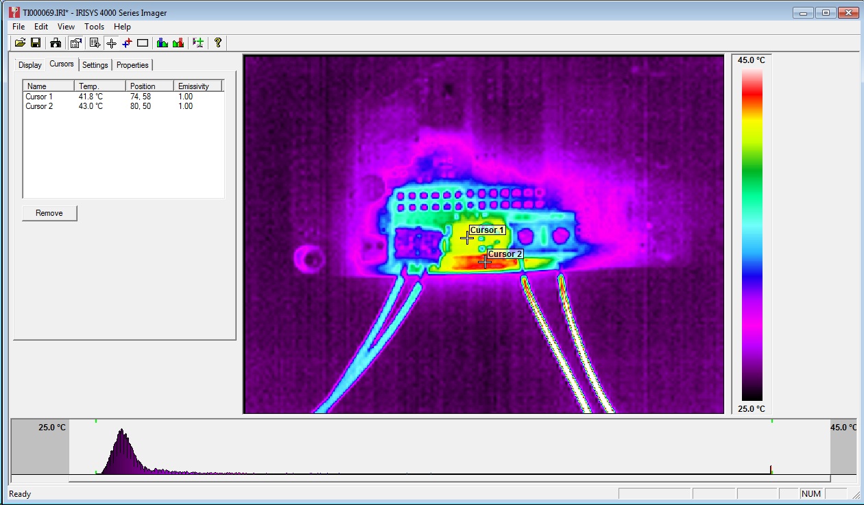
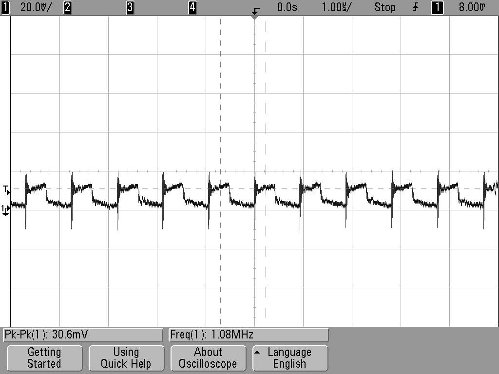
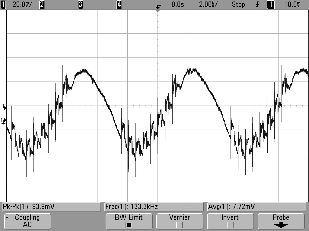
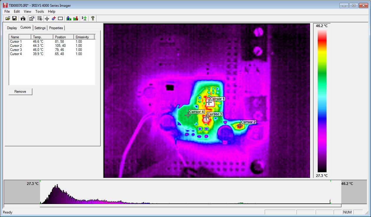
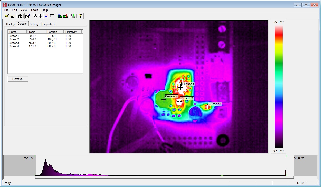
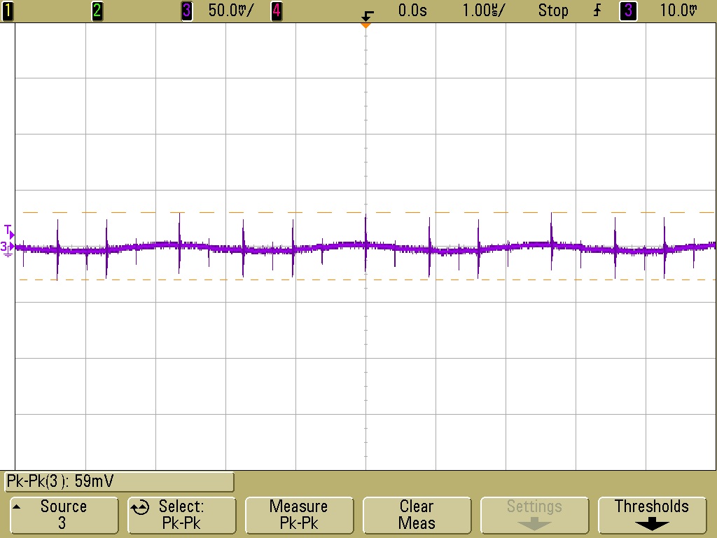
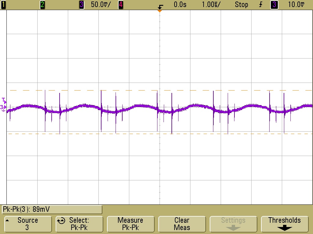
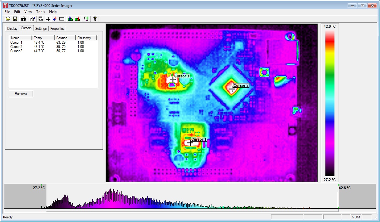
  • Lower noise components and circuit layout used for the 5V BUCK circuit.
  • Complete ground plane - reduce noise and potential ground loops.
  • Switches and power indication LEDS moved to the same edge as the SD/USB/Ethernet for simpler access and indication.
  • VSSA now present on the expansion header. This combined with the changes to the Duex4 0.2a mean that analogue ground is now used for all 7 temperature measurement channels.


Other Changes

Not necessarily improvements but changes to simplify the board or reduce component count:
  • USB is now a simple USB 2.0 device, rather than a Host/Device as before. This was never used on the 0.6 and removing it reduces component count.
  • Removed the IDC headers for the heatbed and motor/hotend wiring loom. The footprints took up valuable board space and I am not aware of a printer that used a complex loom terminated in a single IDC.
  • The FAN MOSFETs are now PMV40UN2R FETs which are lower power but more than adequate for fans and other lower current devices. They also don't use a second mosfet to increase turn on voltage, like in the 0.6 design, as that was overkill. This means they are inverting (use M106 I1 to change)
  • Extruder thermistor headers and fan headers moved towards the middle of the board to allow for the same board size as the Duet 0.6 to be used.
  • In order to support a 7th heater channel (Extruder 6) along with two PWM fans the PWM pin had to be shared. This means that you can't run 6 extruders AND 2 PWM fans at the same time.

Board Connections

Duet 0.8.5 Connections


The expansion header pins have changed slightly as shown in the picture below:


Duet 0.8.5 Expansion header pins back view
The pins on the Duex 0.6 that went to the extruder E1 on the Duex4 have been diverted to E1 on the Duet 0.8.5. New pins now go to E5 in place of E1 on the Duex4


Opensource Hardware

In the same manner as the Duet 0.6 the Duet is based on the Arduino Due, and the KiCAD source files are released under the CERN OHL 1.2 license, which means you are free to modify them and distribute products based on them, as long as you share your modifications under the same license. We believe this is a much more appropriate license for Open Hardware than a Creative Commons/GPL or other licence based around copyright.

The Duet 0.8.5 source files are available on GitHub so feel free to fork the project and modify away!

Duet 0.8.5 developed with the Open Source KiCAD EDA suite


KiCAD has continued to improve since I started to develop hardware over 2 years ago. It is a powerful, Open Source design suite which means that the source files for the Duet are open for anyone to use and so is the software needed to modify them.

Firmware & Webinterface

The Duet 0.8.5 runs RepRapFirmware, the linked github page has the Think3dPrint3d latest version based on David Crocker's fork. I have made the changes required to support the additional pins, extruder multiple PWM fans and hopefully this will be merged into David's fork shortly.

The firmware has also improved substantially since the Duet 0.6. The majority of these improvements Think3dprint3d can take no credit for as they are the work of the RepRap community.

David Crocker has done excellent work in optimising the firmware and implementing segmentation free support for Delta printers. Old-style firmwares rely on segmentation to calculate movement but this can add printing artefacts. On David's fork the delta transform is calculated for each step, i.e. it's segmentation free, and thus the quality is higher. This is only possible due to the higher processing speed of 32 bit electronics.

Christian Hammacher (on the RepRap forums as zombiepantslol) has done a fantastic job continuing to improve the web interface:

Updated RepRapFirmware Web Interface with 6 extruders - Large Screen (PC) view
I am now also using the webinterface from my mobile, here are a couple of screenshots of that:

RepRapFirmware Web Interface on Mobile

RepRapFirmware Web Interface on Mobile - Print page


Production & Availability

The Duet 0.8.5 boards are being produced for us in the UK by a local electronics manufacturer. The first batch is finished and available on our website:


Also available as a bundle with the Duex4, and I will be very excited to see someone using all 6 extruders!


Thursday, 16 January 2014

Duet on board power supply testing

There have been a number of discussions on the reprap forum (1,2,3 for starters) about the effect of electrical noise causing hanging/freezing on the Duet board requiring reset attributed to this. Radian originally highlighted that a significant spike on the 12V line was caused by the switch of of the Heated Bed FET could be the cause.

We have done  quite a bit of investigation now into this particular effect, its causes and options to reduce it which is covered below. All the scope plots were recorded by Andy, one of the Duet designers. Throughout the green trace is the voltage under investigation and the purple trace is the heated bed current.

The relevant portion of the schematic is shown here for quick reference, full design files are on Github:


Bed FET Switching Transient Spike

Due to the fast switch off of the MOSFET, combined with the inductance of the PCB heatbed (average measurements 1uH) there is significant ringing (47.8V pp). The FET is avalanching at that point.


12V at he MOSFET Drain during bed switch off
This noise is relatively local to the MOSFET though, at the 12V input connector it is down to 750mV pp.

12V at the input connector

Once through the buck DC-DC convertor on the 5V line the noise is down to 130mV pp.
5V at buck output

and by the time that goes through the 3.3V regulator its down to 63 mV


3.3V at LDO regulator output
 At this point the 3.3V is further filtered and converted onboard the processor to 1.68V.

Mitigating the Spike

Some of these ideas have come form suggestions on the RepRap forums - thanks for the input!

First Andy added an RC snubber across the FET  with a 10nF capacitor and a 10R resistor. This removed the ringing but the large spike was still evident. Adding a catch diode across the heat bed contact made a small additional difference


RC snubber added across FET (10nF + 10R)


Snubber + catch diode across heat bed contacts
Finally R18 (see schematic at the top) was changed for 470R and 100R added in series with the FET gate. This has the effect of speeding up the turn on and slowing down the turn off of the FET. With all of this in place the spike is still significant but as the second trace below shows the noise on the 3.3V line is now only ~18mV

Snubber + catch diode + R18 changed to 470R and 100R added in series with TR2 gate
3.3V LDO output during heated bed switching
So what?

Our assessment at this point is that the 12V spike caused by the heated bed switching is not, in of itself, causing any negative effects to the Duet processor. In addition the avalanching causes minimal additional heating to the FET when "Bang, Bang" switching or low speed (<1KHz) PWM is used. High speed PWM is bad due mainly to the slow turn on time which causes significant heating.

During this testing we had 3 Duet boards using PWM on the heated bed for a number of days with no modifications, those processors have been subjected to hundreds of millions of these noise spike without a single crash and hang. That is not saying that its not possible but there are probably other contributory factors, see "Further Work" below

Further Work

More investigation is needed into the effects of USB ground loops which may be causing some issues. Other USB noise can also cause problems, the investigation by markbee, posted on the forums is a very useful starting point.

The firmware is being continually updated (special thanks to dc42 for all the work he has already done). This has already fixed some causes of Duets hanging so make sure you are using the most up to date firmware if you are having issues.

I must again thank everyone who is contributing so much on the forums!


Monday, 30 December 2013

Duet FET, PSU and Stepper Driver Testing

This blog post is primarily a cut and paste from notes made during the testing of the Duet v0.3 (note the current version is 0.6). I have uploaded the design files for version 0.3 onto the archive area of the github project so the differences between the design tested in these pictures and the current design can be seen.

Normally I would try and get more detail into the post about the design decisions but that will have to wait until a later post.

FETs Testing


FETs are on by default when 3.3V regulator is disconnected as Vgs = 5V (same as when MCU turns FETs on), so software not required. (Note this setup has been replaced in version 0.6 with FETs off by default).

Tested with 10A load gives Vds = 32mV - therefore dissipating 0.32W


32mV at 10A = 3.2mOhm on resistance. As expected from datasheet.Temp measured at ~40C with thermal camera (ambient ~23C):


Track adjacent to FET (carrying input power) got marginally hotter, though nothing to worry about particularly but aim to increase track width on Duet v0.4.

A 20A load would give 1.28W dissipation. i.e. 4 times as much as 10A, therefore expect 50-60C temp rise on FET from ambient. FET rated to 175C.

PSU Testing

Perfectly happy at low loads (<750mA) (note the Arduino Due Power supply only dives a total of 800mA). 12-24V in, 4.98V out. Voltage ripple = ~30mVpk-pk (DC-20MHZ) See scope plot below:


Marginally unstable with 1A or greater load and Vin >16V.
Voltage ripple = ~100mV (DC-20MHz). See scope plot below:


At 1A load, PWM IC temp = ~40C:


At 1.5A load, PWM IC temp = ~60C:


Further testing on 20/06/13:

Inductor L1 swapped from 22uH to 8.2uH. Tested 12V to 24V input and 0A to 1.5A output load.


12V input, 1.5A load, voltage ripple+noise = ~60mVpk-pk (DC-20MHZ) See scope plot below:


24V input, 1.5A load, voltage ripple+noise = ~90mVpk-pk (DC-20MHZ) See scope plot below:

Stepper Motor Testing

Initial testing completed using stepper.ino sketch. Timings changed to 10,000 for CW and 25,000 for CCW steps. An unloaded motor was run for 30mins with these step rates and then a thermal image was taken of Duet board. See below:


The three hot-spots seen in the image are the 3.3V regulator, the MCU and the stepper driver IC. All three showing temps of around 45C.

Note: Other random colourful spots are reflections off shiny surfaces - e.g. button switches and SD card slot. 

Afterward

The main point of posting this now is to inform the discussion on the RepRap forums about potential improvements to the Powersupply:

http://forums.reprap.org/read.php?340,285306

A great example of the benefits of releasing an open source design - really high quality feedback!


Monday, 2 December 2013

Duet - Arduino Due Compatible 3D Printer Electronics

UPDATE: The Duet 0.6 has been superseded by the Duet 0.8.5, see this blog post:
New Duet electronics version 0.8.5


The Duet is a new 3D Printer controller board that is compatible with the Arduino Due. It has been developed by Andy Hingston and Tony Lock from Think3dPrint3d in conjunction with RepRapPro and with much advice from Chris Palmer (Nophead). This 3D Printer controller combines the Arduino Due microcontroller with 4 stepper motor controllers, Ethernet, Hi-Speed SD card slot and more. 
Think3DPrint3D Duet
Duet Main board
An additional expansion board offers a further 4 stepper motor controllers to allow for a total of 5 extruders or up to 8 axis drives.

Duet with Expansion board
Expansion board for up to 5 extruders in total 

Hardware Overview


The Duet runs the 32 bit, ARM core SAM3X8E microprocessor, as found on the Arduino Due. This is a step change from existing controllers using 8 bit mcroprocessors and leaves loads of overhead to do cool things (like run a webserver, run delta bots much faster etc)

Duet 3D Printer Controller Connections
Duet Connections
3D Printer hardware control

On the main board are 4 Allegro A4982 stepper drivers (X,Y,Z,E0), 3 FETs (Heated Bed, E0, Fan), 2 Thermistor inputs (Heated Bed, E0), 4 Endstop channels (X, Y, Z, E). The stepper drive current is electronically controlled with an I2C Digital potentiometer. As an alternative to using screw terminals there are double rows of pin headers for two wiring looms, 1 for the heated bed and one for the rest of the printer. This allows for the easy use of wiring looms to simplify printer assembly.

Connectivity

The USB port is a Hi-Speed A/B type allowing for standard for USB control from a PC and potentially support for USB devices in the future. The SD card socket is fully SD 2.0 compliant, supporting faster access and cards up to 32 GB. A 10/100T Ethernet port allows for network control via an on-board web server.

Power

Power in comprises a 12-24V main input along with connections to control a standard ATX power supply. On board the Duet can use USB for 5V, incoming 5V from the ATX power supply and it has an inbuilt 2A switching power supply to provide 5V to support future expansion (for example powering a connected USB device).

Expansion board

The expansion board has a further 4 A4982 stepper drivers (E1, E2, E3, E4), another I2C digipot, 4 FETs (E1, E2, E3, E4) and corresponding thermistor inputs. It also has a header exposing 3 Serial channels, SPI bus and 2x I2C buses for further expansion.
Expansion board connections

Open Hardware

The Duet hardware design is licensed under the CERN OHW License 1.2: the design is free to be distributed and modified within the terms of this license. All the design files are here on Github.

Duet Open Hardware Logos

Not only is it Open Hardware but it was completely designed using the Open Source software package KiCAD so hacking and building on this design its accessible to all.

A detailed blog post on the hardware design will follow.

Software Overview


The Duet runs RepRap Firmware, a new C++ firmware by Adrian Bowyer. The firmware can be compiled with the Arduino IDE (tested with 1.5.4) or Eclipse and uploaded like other firmware, but the aim is for much of the printer specific information to be set by Gcode which is read on machine start from the SD card.

The software supports receiving GCode from 3 locations:
  1. Over the USB serial port (as current 3D printer controllers do) - making it compatible with software such as Pronterface and Repetier host.
  2. From the SD card, which also stores the web server files and the config files.
  3. From the Ethernet interface via the webserver:
RepRap Firmware web interface

RepRapPro have a video here showing the web interface in use with the Ormerod printer.

The software is adding new features daily, the most recent being added alpha level support for multiple extruder printing - see the T3P3 github, RepRapFirmware, multi extruder branch.

Here is a picture of the first dual extruder print from a Duet and expansion board combo. I will add a video when I have a chance to edit it!


Where to get it

We will stock our Web Shop tomorrow with a limited number of the first Duet production run available for immediate purchase, with expansion boards to follow next week. A larger production run is underway so don't despair if you miss the first batch.

Update: The Duex4 Expansion boards are available on our Web Shop. The source files for the board are on Github.

Update2: Those who are in Germany or Austria can now buy the Duet and Duex4 from RepRap Austria