Normally I would try and get more detail into the post about the design decisions but that will have to wait until a later post.
FETs Testing
FETs are on by default when 3.3V regulator is disconnected as Vgs = 5V (same as when MCU turns FETs on), so software not required. (Note this setup has been replaced in version 0.6 with FETs off by default).
Tested with 10A load gives Vds = 32mV - therefore dissipating 0.32W
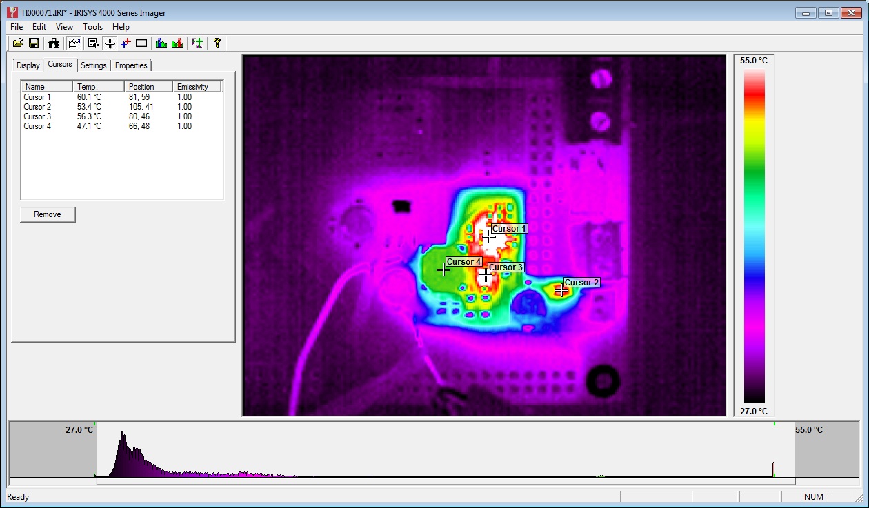
32mV at 10A = 3.2mOhm on resistance. As expected from datasheet.Temp measured at ~40C with thermal camera (ambient ~23C):
Track adjacent to FET (carrying input power) got marginally hotter, though nothing to worry about particularly but aim to increase track width on Duet v0.4.
PSU Testing
Perfectly happy at low loads (<750mA) (note the Arduino Due Power supply only dives a total of 800mA). 12-24V in, 4.98V out. Voltage ripple = ~30mVpk-pk (DC-20MHZ) See scope plot below:
Marginally unstable with 1A or greater load and Vin >16V.
Voltage ripple = ~100mV (DC-20MHz). See scope plot below:

At 1A load, PWM IC temp = ~40C:

At 1.5A load, PWM IC temp = ~60C:

Further testing on 20/06/13:
Inductor L1 swapped from 22uH to 8.2uH. Tested 12V to 24V input and 0A to 1.5A output load.
12V input, 1.5A load, voltage ripple+noise = ~60mVpk-pk (DC-20MHZ) See scope plot below:

24V input, 1.5A load, voltage ripple+noise = ~90mVpk-pk (DC-20MHZ) See scope plot below:

Stepper Motor Testing
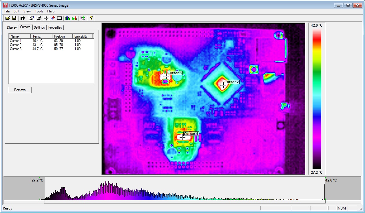
Initial testing completed using stepper.ino sketch. Timings changed to 10,000 for CW and 25,000 for CCW steps. An unloaded motor was run for 30mins with these step rates and then a thermal image was taken of Duet board. See below:

The three hot-spots seen in the image are the 3.3V regulator, the MCU and the stepper driver IC. All three showing temps of around 45C.
Note: Other random colourful spots are reflections off shiny surfaces - e.g. button switches and SD card slot.
Afterward
The main point of posting this now is to inform the discussion on the RepRap forums about potential improvements to the Powersupply:
A great example of the benefits of releasing an open source design - really high quality feedback!
No comments:
Post a Comment
Comments are now moderated to reduce spam, please excuse the additional time this will entail.
Note: only a member of this blog may post a comment.