According to Wikipedia the Kraken is "a legendary sea monster of giant proportions". It is also a new hotend from E3D which has 4 nozzles and is water cooled - packing all that into a form size of modest proportions.
I have been experimenting with the Kraken printing on the Lasercut Mendel90 using the Duet and Duex4 which supports up to 5 extruders. I was lucky enough to get my hands on one of the Krakens while still in beta (thanks Sanjay!) so there may be one or two modifications between the one I have and the final version they are bringing out soon.
 |
| Predicted to be Legendary Hotend |
 |
| Legendary sea monster |
Setup in overview
Modified Lasercut Mendel90: changes include:
- Re-designed X Carriage to accommodate the Kraken.
- Additional extruder wiring loom.
- 4 RepRapPro filament drives
- Duet and Duex4 electronics which can drive up to 5 extruders
- Updated RepRapFirmware for multiextruders
- The Kraken! (with water cooling system)
Results
so far I have done a couple of 4 colour prints
X carriage modifications
The carriage itself has been modified to fit the kraken underneath, secured with 4 M3 fasteners. There is a cutout for the Bowden and water pipes and two more cutouts for the wiring.
I wanted to keep using the extruder wiring loom that the Mendel90 is designed with. This normally plugs into a bracket on the extruder motor on a non-Bowden system, so I had to design a carriage mounted bracket.
This allows for two of Nophead's 15 Way D Type extruder breakout boards to be mounted. The bracket is a bit of a pain to print as it needs support but I like the way it all fits together. This picture shows it part way through assembly.
The OpenSCAD and STL files are shared on our github:
Wiring
The second ribbon cable follows the same route as the original Mendel90 extruder wiring loom.
Ribbon Cable A is the original Mendel90 wiring loom, Ribbon Cable B is a 14 core ribbon cable wired to mirror Ribbon Cable A as shown in the table below. Ribbon A has not changed from my Dual extruder setup and uses the original motor wires to carry the second extruder with the probe circuit carrying the second thermistor.
| Description | Wire | PCB 1 (right side) | Notes |
| E0 Thermistor GND | Ribbon A #4 | P2 Pin 2 (T) | Common with E1 Therm GND |
| E0 Thermistor Signal | Ribbon A #3 | P2 Pin 1 (T) |
|
| E1 Thermistor GND | Ribbon A #4 | P4 Pin 1 (P) | Common with E0 Therm ground. no separate cable at Duex4 end |
| E1 Thermistor Signal | Ribbon A #5 | P4 Pin 2 (P) |
|
| E0 switched GND | Ribbon A #9, 10, 11 | P2 Pin 4 (H) |
|
| E0 +12V | Ribbon A # 6, 7, 8 | P2 Pin 3 (H) |
|
| E1 +12V | Ribbon A #13 | P3 Pin 1 (MR) |
|
| E1 +12V | Ribbon A #14 | P3 Pin 2 (MB) |
|
| E1 switched GND | Ribbon A #15 | P3 Pin 3 (MG) |
|
| E1 switched GND | Ribbon A #16 | P3 Pin 4 (MK) |
|
|
| PCB 2 (left side) |
|
| E2 Thermistor GND | Ribbon B #2 | P2 Pin 2 (T) | Common with E3 Therm GND |
| E2 Thermistor Signal | Ribbon B #1 | P2 Pin 1 (T) |
|
| E3 Thermistor GND | Ribbon B #2 | P4 Pin 1 (P) | Common with E2 Therm ground. no separate cable at Duex4 end |
| E3 Thermistor Signal | Ribbon B #3 | P4 Pin 2 (P) |
|
| E2 switched GND | Ribbon B #7,8,9 | P2 Pin 4 (H) |
|
| E2 +12V | Ribbon B #4,5,6 | P2 Pin 3 (H) |
|
| E3 +12V | Ribbon B #11 | P3 Pin 1 (MR) |
|
| E3 +12V | Ribbon B #12 | P3 Pin 2 (MB) |
|
| E3 switched GND | Ribbon B #13 | P3 Pin 3 (MG) |
|
| E3 switched GND | Ribbon B #14 | P3 Pin 4 (MK) |
|
It is much less pretty at the Duet + Duex4 end:

Both these boards are designed to allow for IDC connectors but the wiring looms to use them are still a work in progress, hence the screw terminals.
The Lasercut Mendel90 was always designed to accommodate 5 filament drives, with the "extruder sandwich" as part of the frame. Although I only need 4 for now I have all 5 mounted for future developments:
 The filament drives fitted are the RepRapPro design for their Mono and Tricolour Mendel.
Firmware
I have extended the RepRap Firmware to accommodate 5 extruders and added one or two legacy commands that other firmwares support. This is definitely still a work in progress to get all the functionality we have become accustomed to with firmware like Marlin.
My fork of the firmware is available here:
https://github.com/T3P3/RepRapFirmware/tree/Multi_Extruder_Test
The Kraken!
The main thing that sets the Kraken apart from other hotends is the "cold end", this is designed to take up to 4 hot ends that can move up and down in the block, secured by two grub screws each. It incorporates a water cooling passage and two "barbs" to take the hoses for the water. The first thing I tested was the water system to ensure it did not leak:
I used fish tank airline silicone tubing because it was easy to get hold of, cheap and flexible. I think any tubing which is flexible enough and fits on the coupling well will do - what will be interesting is the long term effects of the flexing on the tubing. The other end of the tubing has a small pump supplied by E3D and it is just dumped in a water container.
Next I installed the cold block into the x carriage and wired up 4 thermistors and fitted the heater cartridges. I prefer to use axial leaded thermistors (like these) as they are more robust and easy to wire but the heater blocks also have holes for radial leaded thermistors like the EPCOS and tiny ones used in other hotends.
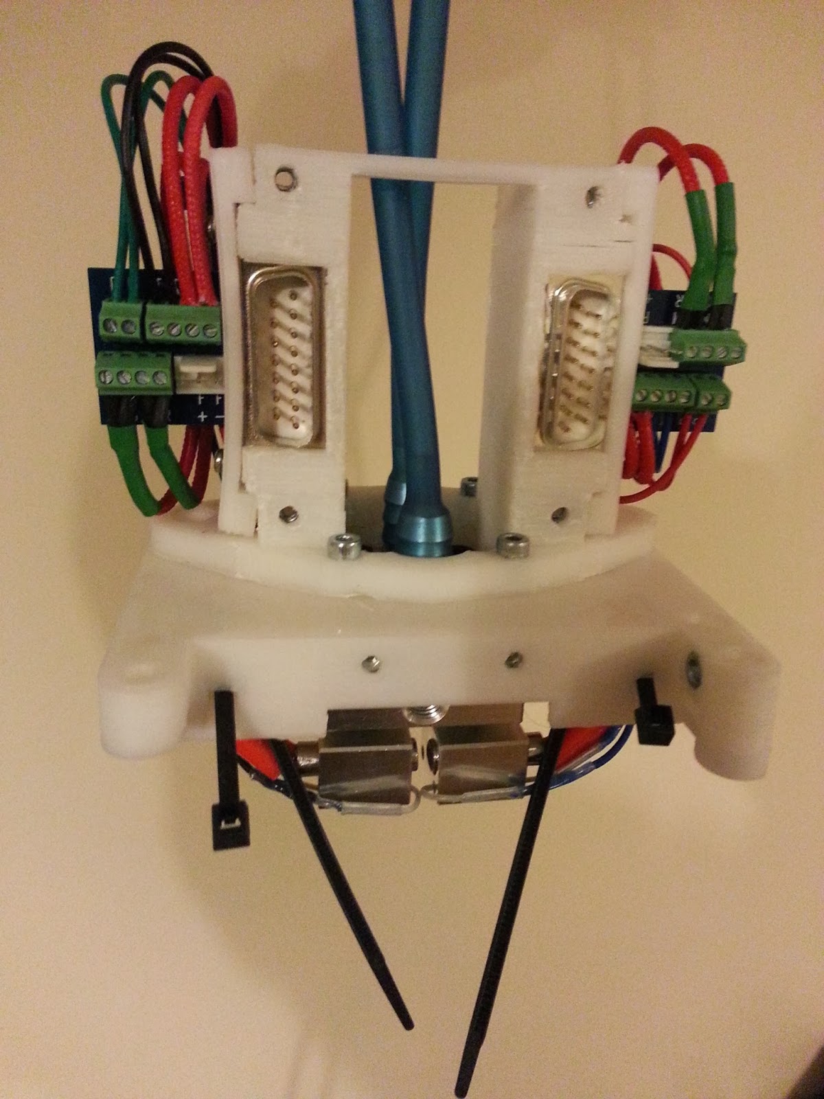
The view from underneath
At this point its more like a Medusa with all the wires and hoses! The D bracket holders and PCBs fit and the 4 M3 fixings for the Kraken hold it all in place (so the 2 M4 holes in the carriage are not required)
I did not fit the Bowden cables yet as it would have been even more unwieldy and the Kraken has a ingenious push fit Bowden connector integrated into the cool block so they can be added later.
I then mounted the X carriage and installed two of the bowden tubes. Leveling the bed is extremely important as the "end effector" is now the size of the square made up of the 4 hot end tips. I started with one hotend tip lower than the other three to make the bed levelling easier.
First print:
You may be able to see that the unused hotend tips are slightly higher. This turned out quite well at 0.2mm layer height:
its "Bucket O' Octopodes (thicker legs)" model by moleofproduction.
Once I had single extruder printing confirmed I centred the carriage on the bed and lowered it until the lowest tip was just touching (making sure everything is at the same temperature). I then dropped the other tips to the same level (relative to the bed) by loosening the grub screws, securing them in place by re-tightening the grub screws. This was a rather fiddly operation but actually much easier than trying to level four individual extruders. (Well, easier than two so it must be easier than four!).
With the 4 nozzles level it was on to a 4 colour print
I have uploaded this test piece to thingiverse. As can be seen Slic3r is building a full- height skirt around it which catches the ooze. That combined with a 20C drop in temperature between the active and standby hotends is reducing the ooze effect. I also cheated in this design as the similar corners of the triangles are 20mm apart, the same spacing as the nozzles.
My next idea was to make up a 4 colour "kraken" scene to try something a bit more difficult. Using OpenSCAD I imported the "Bucket O' Octopodes (thicker legs)" and Daid's "Small OpenSCAD Ship" slightly modified to be easier to print. I cut out the eyes and added some spheres to use another colour and then built up a scene with some "water".
This is the OpenSCAD render
Ignore the weird tentacle shaped gap in the head - it's a rendering artifact.
And then printed it (excuse the camera shake in this picture):
The print with the anti-ooze wall still on:
Not perfect by any stretch! I think it will a big improvement when I design a fan duct for this setup which should help the thin sails to print better.
The ooze wall did not fully catch all the ooze - I think a 30 or 40C change in temperature might be needed but that will take ages for every colour change.
I have also found an issue with extrusion in Slic3r when using multiple extruders - it sometime extrudes a huge amount too much which may account for some of the blobby-ness. Update: not an issue with slic3r - I entered 90 rather than 0.9 in the top infil box!
Plenty more to improve on but it has been really fun setting this up and working with the Kraken - its a great multi nozzle hotend!


.jpg&container=blogger&gadget=a&rewriteMime=image%2F*)


.jpg)