Panelolu on RAMPS
Update: The Panelolu2 has replaced the Panelolu. It is much quicker to install, has adapter boards to no messing with cables and uses less pins. The blog post with the information is here, it is available to buy in our webshop.
The original idea for the Panelolu was based on the PanelMax which works with RAMPS. What I had not got around to doing was determining the changes needed to the pin mapping to cable for the Panelolu to work on RAMPS. Thankfully Ian Stratford has done the hard work and worked it all out.
Update: Ian has also made the Panelolu page on the reprap wiki - thanks!
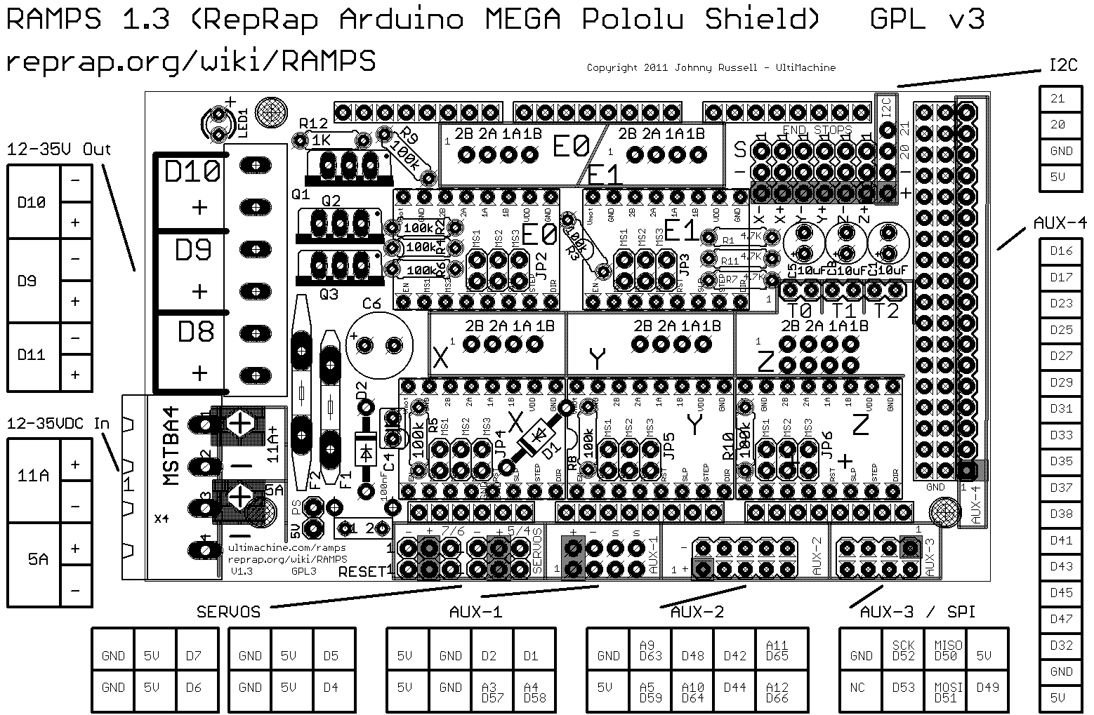
The tables below refer to the RAMPS pin outs from the reprap wiki - the picture is below
The tables below cover the differences between the RAMPS setup and the original instructions: Panelolu on Sanguinololu.
Ribbon Cable number
|
Function
|
Pin Sanguinololu
|
Pin RAMPS
|
1
|
GND
|
GND
|
NA
|
2
|
12V
|
12V
|
NA
|
3
|
LCD 1 (VSS - Ground)
LCD 5 (RW - Read/Write)
LCD 16 (K - Backlight Anode-)
Breadboard GND for encoder,
switch, contrast, reset.
|
GND
|
GND (AUX-4)
|
4
|
LCD 2 (VDD +3.3 to +5v)
5V on breadboard, for brightness
|
5V
|
5V (AUX-4)
|
5
|
LCD 14 (DB7 - data bit)
|
A4
|
D29
|
6
|
LCD 4 (RS - register select)
|
PWM D12
|
D16
|
7
|
LCD 13 (DB6 - data bit)
|
A3
|
D27
|
8
|
Encoder1
|
TX1 D11
|
D35
|
9
|
LCD 12 (DB5 - data bit)
|
A2
|
D25
|
10
|
Encoder2
|
RX1 D10
|
D37
|
11
|
LCD 11 (DB4 - data bit)
|
A1
|
D23
|
12
|
LCD 6 (E - clock)
|
SDA D17
|
D17
|
13
|
SD (CS pin)
|
A0
|
D53
|
14
|
(via SDSL plug, NC) Encoder
click
|
SCL D16
|
D31
|
15
|
(via SDSL plug, NC)
|
||
16
|
(via SDSL plug, NC)
|
||
17
|
SD Ground
|
GND
|
GND
|
18
|
(via SDSL plug, NC) Reset
|
RST
|
No RST pin?
|
19
|
SD (DI pin)
|
MOSI
|
MOSI D51
|
20
|
SD (SCK pin)
|
SCK
|
SCK D52
|
21
|
SD 5V
|
5V
|
5V
|
22
|
SD (DO pin)
|
MISO
|
MISO D50
|
23
|
NA
|
NA
|
|
24
|
NA
|
NA
|
|
Other
|
LCD 3 (VO – contrast adjuster)
to C on breadboard
|
||
Other
|
LCD 15 (A – Backlight Anode+) to
B on breadboard (brightness)
|
RAMPS
AUX-4
Ribbon Cable number
|
Function
|
Pin Sanguinololu
|
Pin RAMPS
|
6
|
LCD 4 RS (register select)
|
PWM D12
|
D16
|
12
|
LCD 6 E (clock)
|
SDA D17
|
D17
|
11
|
LCD 11 DB4
|
A1
|
D23
|
9
|
LCD 12 DB5
|
A2
|
D25
|
7
|
LCD 13 DB6
|
A3
|
D27
|
5
|
LCD 14 DB7
|
A4
|
D29
|
14
|
SD, encoder click
|
SCL D16
|
D31
|
(Piezo Buzzer +)
|
D33
|
||
8
|
Encoder1
|
TX1 D11
|
D35
|
10
|
Encoder2
|
RX1 D10
|
D37
|
3
|
Ground
|
GND
|
GND
|
4
|
5V
|
5V
|
5V
|
RAMPS
AUX-3 / SPI
Ribbon Cable number
|
Function
|
Pin Sanguinololu
|
Pin RAMPS
|
17
|
SD Ground
|
GND
|
GND
|
NC
|
NC
|
||
20
|
SD (SCK pin)
|
SCK
|
SCK D52
|
13
|
SD (CS pin)
|
A0
|
D53
|
22
|
SD (DO pin)
|
MISO
|
MISO D50
|
19
|
SD (DI pin)
|
MOSI
|
MOSI D51
|
21
|
SD 5V
|
5V
|
5V
|
NC
|
D49
|
To quote Ian
"I have managed to connect up the Panelolu kit to my RAMPS board with great success! Everything works except the reset button, as there is no reset pin on RAMPS. I added a piezo electric buzzer as well (from an old PC). Cabling is pretty straightforward, I just needed to trace the connection to the right pin. I built the Panelolu kit as per the Sanguinololu instructions, then used a couple of different sources to work out the correct pins on the RAMPS board. Then all I had to do was uncomment the #define ULTIPANEL line in Marlin. I did check the pins.h file, but it's already all in there for RAMPS. Worked first time!!"Its now on my todo list to make up a cable to connect to RAMPS, something I intend to use on a dual extruder M90.
Printrboard issues
One of our customers, Bernardo, highlighted an issue with the Printrboard design: the Y-endstop is on the SS pin. Bernardo found the solution on Colin Bradburne's blog which I wont repeat here but if you are intending on using an SD card with Printrboard it is well worth reading his blog.