UPDATE: The Duet 0.6 has been superseded by the Duet 0.8.5, see this blog post:
New Duet electronics version 0.8.5
The Duet is a new 3D Printer controller board that is compatible with the Arduino Due. It has been developed by Andy Hingston and Tony Lock from Think3dPrint3d in conjunction with RepRapPro and with much advice from Chris Palmer (Nophead). This 3D Printer controller combines the Arduino Due microcontroller with 4 stepper motor controllers, Ethernet, Hi-Speed SD card slot and more.
 |
| Duet Main board |
An additional expansion board offers a further 4 stepper motor controllers to allow for a total of 5 extruders or up to 8 axis drives.
 |
| Expansion board for up to 5 extruders in total |
Hardware Overview
The Duet runs the 32 bit, ARM core SAM3X8E microprocessor, as found on the Arduino Due. This is a step change from existing controllers using 8 bit mcroprocessors and leaves loads of overhead to do cool things (like run a webserver, run delta bots much faster etc)
 |
| Duet Connections |
3D Printer hardware control
On the main board are 4 Allegro A4982 stepper drivers (X,Y,Z,E0), 3 FETs (Heated Bed, E0, Fan), 2 Thermistor inputs (Heated Bed, E0), 4 Endstop channels (X, Y, Z, E). The stepper drive current is electronically controlled with an I2C Digital potentiometer. As an alternative to using screw terminals there are double rows of pin headers for two wiring looms, 1 for the heated bed and one for the rest of the printer. This allows for the easy use of wiring looms to simplify printer assembly.
Connectivity
The USB port is a Hi-Speed A/B type allowing for standard for USB control from a PC and potentially support for USB devices in the future. The SD card socket is fully SD 2.0 compliant, supporting faster access and cards up to 32 GB. A 10/100T Ethernet port allows for network control via an on-board web server.
Power
Power in comprises a 12-24V main input along with connections to control a standard ATX power supply. On board the Duet can use USB for 5V, incoming 5V from the ATX power supply and it has an inbuilt 2A switching power supply to provide 5V to support future expansion (for example powering a connected USB device).
Expansion board
The expansion board has a further 4 A4982 stepper drivers (E1, E2, E3, E4), another I2C digipot, 4 FETs (E1, E2, E3, E4) and corresponding thermistor inputs. It also has a header exposing 3 Serial channels, SPI bus and 2x I2C buses for further expansion.
 |
| Expansion board connections |
Open Hardware
The Duet hardware design is licensed under the CERN OHW License 1.2: the design is free to be distributed and modified within the terms of this license. All the design files are here on Github.
Not only is it Open Hardware but it was completely designed using the Open Source software package KiCAD so hacking and building on this design its accessible to all.
A detailed blog post on the hardware design will follow.
Software Overview
The Duet runs RepRap Firmware, a new C++ firmware by Adrian Bowyer. The firmware can be compiled with the Arduino IDE (tested with 1.5.4) or Eclipse and uploaded like other firmware, but the aim is for much of the printer specific information to be set by Gcode which is read on machine start from the SD card.
The software supports receiving GCode from 3 locations:
- Over the USB serial port (as current 3D printer controllers do) - making it compatible with software such as Pronterface and Repetier host.
- From the SD card, which also stores the web server files and the config files.
- From the Ethernet interface via the webserver:
 |
| RepRap Firmware web interface |
RepRapPro have a video here showing the web interface in use with the Ormerod printer.
The software is adding new features daily, the most recent being added alpha level support for multiple extruder printing - see the T3P3 github, RepRapFirmware, multi extruder branch.
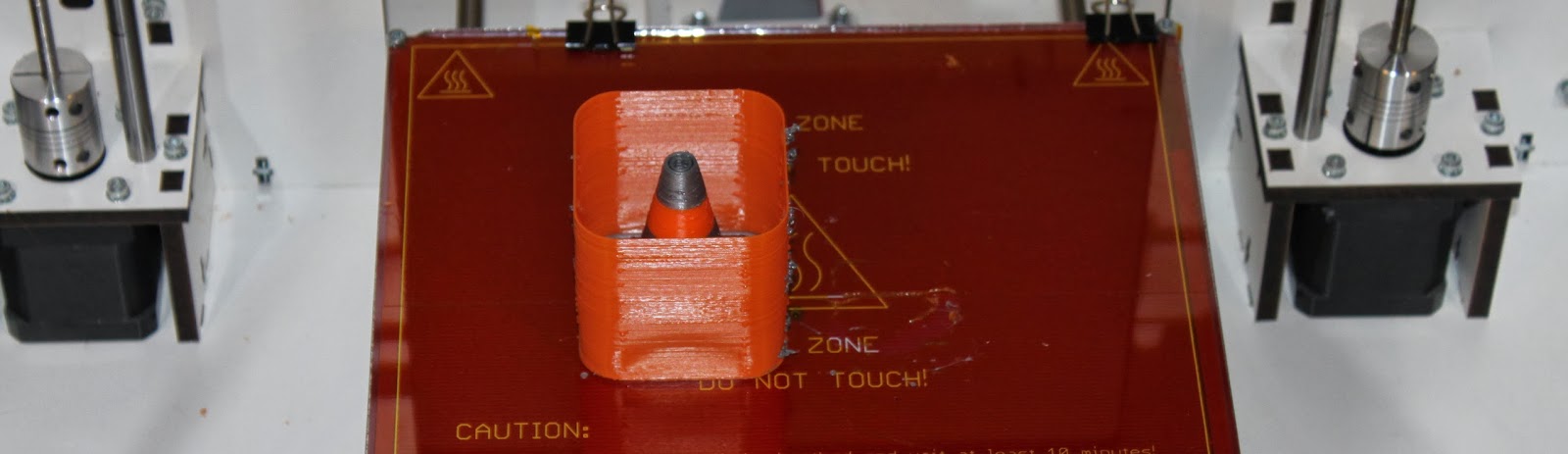
Here is a picture of the first dual extruder print from a Duet and expansion board combo. I will add a video when I have a chance to edit it!
Where to get it
We will stock our Web Shop tomorrow with a limited number of the first Duet production run available for immediate purchase, with expansion boards to follow next week. A larger production run is underway so don't despair if you miss the first batch.
Update: The Duex4 Expansion boards are available on our Web Shop. The source files for the board are on Github.
Update2: Those who are in Germany or Austria can now buy the Duet and Duex4 from RepRap Austria