Monday 30 December 2013

Duet FET, PSU and Stepper Driver Testing

This blog post is primarily a cut and paste from notes made during the testing of the Duet v0.3 (note the current version is 0.6). I have uploaded the design files for version 0.3 onto the archive area of the github project so the differences between the design tested in these pictures and the current design can be seen.

Normally I would try and get more detail into the post about the design decisions but that will have to wait until a later post.

FETs Testing


FETs are on by default when 3.3V regulator is disconnected as Vgs = 5V (same as when MCU turns FETs on), so software not required. (Note this setup has been replaced in version 0.6 with FETs off by default).

Tested with 10A load gives Vds = 32mV - therefore dissipating 0.32W


32mV at 10A = 3.2mOhm on resistance. As expected from datasheet.Temp measured at ~40C with thermal camera (ambient ~23C):


Track adjacent to FET (carrying input power) got marginally hotter, though nothing to worry about particularly but aim to increase track width on Duet v0.4.

A 20A load would give 1.28W dissipation. i.e. 4 times as much as 10A, therefore expect 50-60C temp rise on FET from ambient. FET rated to 175C.

PSU Testing

Perfectly happy at low loads (<750mA) (note the Arduino Due Power supply only dives a total of 800mA). 12-24V in, 4.98V out. Voltage ripple = ~30mVpk-pk (DC-20MHZ) See scope plot below:


Marginally unstable with 1A or greater load and Vin >16V.
Voltage ripple = ~100mV (DC-20MHz). See scope plot below:


At 1A load, PWM IC temp = ~40C:


At 1.5A load, PWM IC temp = ~60C:


Further testing on 20/06/13:

Inductor L1 swapped from 22uH to 8.2uH. Tested 12V to 24V input and 0A to 1.5A output load.


12V input, 1.5A load, voltage ripple+noise = ~60mVpk-pk (DC-20MHZ) See scope plot below:


24V input, 1.5A load, voltage ripple+noise = ~90mVpk-pk (DC-20MHZ) See scope plot below:

Stepper Motor Testing

Initial testing completed using stepper.ino sketch. Timings changed to 10,000 for CW and 25,000 for CCW steps. An unloaded motor was run for 30mins with these step rates and then a thermal image was taken of Duet board. See below:


The three hot-spots seen in the image are the 3.3V regulator, the MCU and the stepper driver IC. All three showing temps of around 45C.

Note: Other random colourful spots are reflections off shiny surfaces - e.g. button switches and SD card slot. 

Afterward

The main point of posting this now is to inform the discussion on the RepRap forums about potential improvements to the Powersupply:

http://forums.reprap.org/read.php?340,285306

A great example of the benefits of releasing an open source design - really high quality feedback!


Monday 2 December 2013

Duet - Arduino Due Compatible 3D Printer Electronics

UPDATE: The Duet 0.6 has been superseded by the Duet 0.8.5, see this blog post:
New Duet electronics version 0.8.5


The Duet is a new 3D Printer controller board that is compatible with the Arduino Due. It has been developed by Andy Hingston and Tony Lock from Think3dPrint3d in conjunction with RepRapPro and with much advice from Chris Palmer (Nophead). This 3D Printer controller combines the Arduino Due microcontroller with 4 stepper motor controllers, Ethernet, Hi-Speed SD card slot and more. 
Think3DPrint3D Duet
Duet Main board
An additional expansion board offers a further 4 stepper motor controllers to allow for a total of 5 extruders or up to 8 axis drives.

Duet with Expansion board
Expansion board for up to 5 extruders in total 

Hardware Overview


The Duet runs the 32 bit, ARM core SAM3X8E microprocessor, as found on the Arduino Due. This is a step change from existing controllers using 8 bit mcroprocessors and leaves loads of overhead to do cool things (like run a webserver, run delta bots much faster etc)

Duet 3D Printer Controller Connections
Duet Connections
3D Printer hardware control

On the main board are 4 Allegro A4982 stepper drivers (X,Y,Z,E0), 3 FETs (Heated Bed, E0, Fan), 2 Thermistor inputs (Heated Bed, E0), 4 Endstop channels (X, Y, Z, E). The stepper drive current is electronically controlled with an I2C Digital potentiometer. As an alternative to using screw terminals there are double rows of pin headers for two wiring looms, 1 for the heated bed and one for the rest of the printer. This allows for the easy use of wiring looms to simplify printer assembly.

Connectivity

The USB port is a Hi-Speed A/B type allowing for standard for USB control from a PC and potentially support for USB devices in the future. The SD card socket is fully SD 2.0 compliant, supporting faster access and cards up to 32 GB. A 10/100T Ethernet port allows for network control via an on-board web server.

Power

Power in comprises a 12-24V main input along with connections to control a standard ATX power supply. On board the Duet can use USB for 5V, incoming 5V from the ATX power supply and it has an inbuilt 2A switching power supply to provide 5V to support future expansion (for example powering a connected USB device).

Expansion board

The expansion board has a further 4 A4982 stepper drivers (E1, E2, E3, E4), another I2C digipot, 4 FETs (E1, E2, E3, E4) and corresponding thermistor inputs. It also has a header exposing 3 Serial channels, SPI bus and 2x I2C buses for further expansion.
Expansion board connections

Open Hardware

The Duet hardware design is licensed under the CERN OHW License 1.2: the design is free to be distributed and modified within the terms of this license. All the design files are here on Github.

Duet Open Hardware Logos

Not only is it Open Hardware but it was completely designed using the Open Source software package KiCAD so hacking and building on this design its accessible to all.

A detailed blog post on the hardware design will follow.

Software Overview


The Duet runs RepRap Firmware, a new C++ firmware by Adrian Bowyer. The firmware can be compiled with the Arduino IDE (tested with 1.5.4) or Eclipse and uploaded like other firmware, but the aim is for much of the printer specific information to be set by Gcode which is read on machine start from the SD card.

The software supports receiving GCode from 3 locations:
  1. Over the USB serial port (as current 3D printer controllers do) - making it compatible with software such as Pronterface and Repetier host.
  2. From the SD card, which also stores the web server files and the config files.
  3. From the Ethernet interface via the webserver:
RepRap Firmware web interface

RepRapPro have a video here showing the web interface in use with the Ormerod printer.

The software is adding new features daily, the most recent being added alpha level support for multiple extruder printing - see the T3P3 github, RepRapFirmware, multi extruder branch.

Here is a picture of the first dual extruder print from a Duet and expansion board combo. I will add a video when I have a chance to edit it!


Where to get it

We will stock our Web Shop tomorrow with a limited number of the first Duet production run available for immediate purchase, with expansion boards to follow next week. A larger production run is underway so don't despair if you miss the first batch.

Update: The Duex4 Expansion boards are available on our Web Shop. The source files for the board are on Github.

Update2: Those who are in Germany or Austria can now buy the Duet and Duex4 from RepRap Austria

Thursday 31 October 2013

Dual Extruders on the Lasercut Mendel90

The Lasercut Mendel90 was designed with a mount for up to 5 bowden extruders on the "extruder sandwich". So far I have been working with dual extruders: this is what the printer looks like in overview:


Here are some test prints with objects downloaded from thingiverse. The printer is also a remix on thingiverse.


Dual Extrusion dice on the Lasercut Mendel90
Dual extrusion dice by davemenc

Dual Extrusion cat on the Lasercut Mendel90
Two colour standing cat by nervoussystem

Dual Extrusion traffic cones on the Lasercut Mendel90
Traffic Cone for Dual Extrusion by CocoNut
As can be seen there are still some issues with ooze - pretty much like all dual extrusion systems out there but I have managed to counteract a lot of it by building a skirt all the way up the object and cooling the inactive nozzle.


Dual Extruders


The hot ends are the RepRapPro design, specifically meant for 1.75mm bowden systems and well proven on their printers.


RepRapPro hot ends mounted on the Lasercut Mendel90

I have also used RepRapPro mini extruders which are nice and compact with the inner gear mechanism.


RepRapPro mini extruder as mounted on the Lasercut Mendel90

The only changes I have made in the extrusion system as a whole is the bowden tube is more than twice as long to accommodate the difference in extruder mounting position and printer height.


Modified X Carriage


The main change to the Lasercut Mendel90 itself is a modified X carriage to mount the hot ends, including a mount for the breakout circuit board.


Lasercut Mendel90 Dual Extrusion X Carriage


The OpenSCAD render below shows the main components including the locations for the hot ends (in transparent grey).

Lasercut Mendel90 Dual Extrusion X Carriage OpenSCAD Render


Although the carriage belt attachment points have been moved slightly closer together the same length of belt will still fit. The new printed parts required are shown below: the belt fixings, bearings and breakout PCB can all be reused. The fan mount is very simple and not particularly effective - it uses a 40mm fan which only blows in the general area of the object being extruded.

 I have forked the Lasercut Mendel90 code on Github as "dual" and uploaded the changes (the stls that have "RRPE" in their files names.

Lasercut Mendel90 Dual Extrusion X Carriage OpenSCAD Plate

Wiring and Firmware changes

The extruders wired into the existing PCB utilizing the original E motor connections to carry the second heater current and the probe connection for the second thermistor:

Update for ease of understanding:
For reference the circuit board is labelled as follows, where the red numbers are not printed on the PCB


On the connector it should look like this:


More detail in the table below:

Description
RAMPS
Wire
PCB (marking & red numbering)
E0 Thermistor GND
T0 (pin1)
Ribbon 4
T Pin 2
E0 Thermistor Signal
T0 (pin2)
Ribbon 3
T Pin 1
E1 Thermistor GND
NC
Ribbon 4
P Pin 1
E1 Thermistor Signal
T2 (pin6)
Ribbon 5
P Pin 2
E0 switched GND
D10  -
Ribbon 9, 10, 11
H Pin 2
E0 +12V
D10 +
Ribbon 6, 7, 8
H Pin 1
E1 +12V
D9 +
Ribbon 13
MR Pin
E1 +12V
D9 +
Ribbon 14
MB Pin
E1 switched GND
D9 -
Ribbon 15
MG Pin 3
E1 switched GND
D9 -
Ribbon 16
MK Pin 4
E0, E1 always on Fan +
NC
Ribbon 6, 7, 8
H Pin 1
E0 always on Fan -
NC
Ribbon 3
T Pin 2
E1 always on Fan -
NC
Ribbon 4
P Pin 1

The Lasercut Mendel90 kits use 26 AWG ribbon cable, rather than 28 AWG, which means the cabling can carry a higher current and is more than capable of the additional requirements of a hot end rather than a motor.

As there are already ground and +12V connections on the PCB the extruder cooling fans which are "always on" can be wired in, sharing the screw terminal spaces with the thermistor GND and hotend +12V. I was initially concerned that this arrangement might add significant noise to the thermistor circuits and degrade performance but I have noticed no adverse effects.

At the RAMPS end I took the software controlled fan cable from D9, put a plug on it and plugged it into T1 on the Panelolu2 adapter board. In addition the previously unconnected "probe" cable (wire 5 in the ribbon cable) has a plug put on it and then plugged into pin 6 on the T0-T1-T2 6 pin strip.

The firmware needs to be changed to use dual extruders on RAMPS (set "#define MOTHERBOARD 34 in Configuration.h and "#define EXTRUDERS 2" in Configuration_adv.h.


Filament management


The parametric spool holder comes in useful, although the bearings are not required for these light spools:


Lasercut Mendel90 Dual Extrusion Filament

I have also used some PTFE tubing as filament guides from the spools to the mini extruders.


How to implement it on your Mendel90

As this is still a work in progress I will not go into the fine detail of how to do it but hopefully this summary and the pictures will set anyone who wants to give it a go on the right track.
  • Print the parts for the X carriage and RepRapPro mini extruder.
  • Get hold of a two hotend kits. (a link to the RepRapPro eMakershop listing - similar hotend kits may be available elsewhere). You will need ptfe tube about 300mm long for each one, id 2.0mm od 4.0mm
  • Get hold of the vitamins needed for the mini extruders.
  • Assemble the mini extruders and mount on the Mendel90. If you have a laser cut Mendel90 this is straightforward. Any two positions will work:
  • Change the existing X carriage and extruder for the new x carriage. The fixings, belt and PCB can be re-used, and the E motor can be re-used on one of the mini extruders.
  • Wire it up according to the wiring information above.
  • RepRapPro has a good tutorial on slicing multi material files and setting the extruder heights and offsets, although I simply used a single walled cube, added twice to a multi material file and adjusted the offset until both walls printed on top of one another in X and Y.

Next Steps

The printer is working well in dual extrusion mode and the files are on github. I am really looking forward to see more Mendel90s out there with dual extrusion mods.  That said I have no intention of stopping here. Still on the todo list:
  • A better fan bracket that focuses the air on the extruded part, like the original Mendel90 one.
  • Improve the tool change gcode I use in Slic3r and tune the hot ends' PID, ooze temperature, etc to improve print quality and reduce print time.
  • 4 or 5 extruder carriage design - I will probably common the "cold" part of the hotend to reduce the number of fans and get the nozzles closer together.
  • New cabling plan for a 4 or 5 extruder setup.
  • Demonstrate the new electronics - more to follow on this in a couple of weeks.
  • Finish off the filament management with a guide incorporating a sponge cleaner
  • Design some 4 or 5 colour objects.
  • Ask RichRap for his "ultra easy dual mixer hotend" design!
All this will take some time so don't hold your breath! If you are just starting with 3D printing, or looking to make largely functional objects then I recommend staying with a single extruder system such as that on the standard Lasercut Mendel90.

Sunday 27 October 2013

OpenSCAD - Intro and Example: Designing a filament holder

Over the last few years I have increasingly used OpenSCAD for creating designs of 3D objects. Like many others I was initially put off by the lack of a WYSIWYG point and click interface - it takes time to get used to this scripted method of working.


The OpenSCAD design environment
OpenSCAD - scripted 3D CAD


A common question in forum posts is "why bother", a point and click CAD program is easier to use. For me the advantages come down to these key reasons:

  • Parametrization - Scripted CAD is at the core of the Thingiverse customiser and working with parameters is easy and natural to do when using a programming based approach.
  • Code re-use - Useful elements of designs can be used again and again, as you would with a library of functions in a program. A change to the library can easily be cascaded down to designs which use it.
  • Collaboration - The key advantage, tools like Git can be used to fork and merge the code. Many people can work on the same project in a robust way a method proven in software development.
Like everything its not perfect, I can see the following disadvantages in comparison to a point and click CAD program:
  • Not intuitive to start with - If you are used to learning a program by clicking on stuff to see what happens, as I do for most programs, it can be frustrating.
  • There is no simple way to import or export model files to other non scripted CAD programs other than as an .stl file - fine for 3d printing but not for people who want to use these other tools.
The rest of this (long!) post is a worked example using OpenSCAD to design a filament spool holder for the Lasercut Mendel90. I hope this will help to ease the transition into scripted CAD for those just starting out. This is not meant to replace the manual, or even be a tutorial of all functions. The OpenSCAD documentation is a comprehensive reference and links to a number of tutorials and other worked examples. The final filament holder code is available on github, and its a thing in the thingiverse.

A preview of what the spool holder looks like mounted on the printer:


On to the example!

Monday 21 October 2013

Mendel90 Lasercut - Calibration

Following on from my last post which gave an overview of the Lasercut Mendel90, this post outlines the steps to take to commission and calibrate the printer.

Fortunately, as the laser cutting process standardises the frame there are only a few steps to get up and running.

Software


The Mendel90 Lasercut is not tied to a specific set of software and there are many great software packages out there for preparing 3D models for printing, for controlling the printer itself, and even for the firmware that runs on the electronics. The software covered here is what we have tested the most and recommend. The generation of the 3D models to print is outside of the scope of this post; a good place to start is Thingiverse which has many free models to download.

Slicing software

Slic3r takes a 3D model file as input and generates the "G Code" that instructs the printer. It is free and open source software that is constantly being improved and is available in versions for Windows,  Linux and Mac OSX.  Using this example of a herringbone gear set, the 3D model in "stl" format looks like this:


Slic3r allows you to set how you want the object printed, for example, you should set the layer thickness, density of infill, speed etc.


It produces text based instructions that look like this (a small excerpt from a file):
....
G1 Z0.250 F7800.000
G1 X60.415 Y89.757
G1 F1800.000 E1.00000
G1 X100.085 Y67.787 F1260.000 E11.03416
G1 X100.585 Y67.567 E11.15503
G1 X101.105 Y67.397 E11.27608
....
The G Code is simply a list of instructions which the printer follows one by one. There are many codes - the list on the RepRap Wiki is pretty comprehensive, but to get started you don't need to know this in detail as Slic3r handles it all automatically. 

We distribute a profile for Slic3r with the M90LC kit that allows you to get up and running quickly and the Slic3r manual is comprehensive.

Printer Control Software

The printer does not need a PC to run, as it can be controlled directly from the Panelolu2. However it is quicker and easier to control the printer with a PC for the initial calibration. To do this we use Pronterface which is part of Printrun. This is also available for Windows, Linux and Mac OSX.


Pronterface allows you to directly control the printer, move the axes, set the bed and extruder temperatures and load files to print. A nice feature is that it will render the G-code of a loaded file so it can be examined before printing. The screen capture below shows a slice through the herringbone gear G code


Firmware

The RAMPS controller board on the printer runs Marlin firmware, which takes the incoming G-code from a connected computer or the SD card on the Panelolu2 and acts on it. In order for Marlin to function correctly it needs to be configured with the information about the printer it is controlling. We supply a version of Marlin with all these configuration changes made and only two parameters need to be tweaked during calibration. For an overview of the basic configuration changes possible, see this blog post.

The Arduino software environment is used to upload the firmware to the board. Firmware is updated once during calibration and then should not need further configuration unless you want to take advantage of new features in future firmware or modify your printer.

Commissioning

Before calibration a number of simple tests are run to ensure everything is hooked up right.

Communication in Pronterface: on connection the following should be displayed:
Connecting..
start
Printer is now online.
Marlin 1.0.0
echo: Last Updated: Oct  8 2013 08:22:09 | Author: (T3P3, M90LC v1.0)
Compiled: Oct  8 2013
echo: Free Memory: 4340  PlannerBufferBytes: 1232
echo:Hardcoded Default Settings Loaded<
echo:Steps per unit:
echo:  M92 X80.00 Y80.00 Z4000.00 E520.00
echo:Maximum feedrates (mm/s):
echo:  M203 X300.00 Y300.00 Z3.20 E45.00
echo:Maximum Acceleration (mm/s2):
echo:  M201 X1000 Y1000 Z10 E45
echo:Acceleration: S=acceleration, T=retract acceleration
echo:  M204 S1000.00 T3000.00
echo:Advanced variables: S=Min feedrate (mm/s), T=Min travel feedrate (mm/s), B=minimum segment time (ms), X=maximum XY jerk (mm/s),  Z=maximum Z jerk (mm/s),  E=maximum E jerk (mm/s)
echo:  M205 S0.00 T0.00 B20000 X20.00 Z0.40 E5.00
echo:Home offset (mm):
echo:  M206 X0.00 Y0.00 Z0.00
echo:PID settings:
echo:   M301 P38.60 I4.55 D81.79
echo:SD init fail

Reading through this list you will see that it tells you what most of your Marlin configuration.h settings are.

The axes are then checked to ensure they trigger the limit switches, move in the right direction when commanded and that the Z axis limit switch is not too high. The extruder and bed are heated up. Once its all confirmed to work as expected the next step is calibration.

Calibration - Step 1


First the X and Y axis are set so that the extruder is the same distance above the print bed at every point. This is made simpler by using 3 point mounting for the bed and by leveling the X axis on the Z rods.


Using a sheet of paper as a feeler gauge, the distance between the extruder and the bed is set to be equal at X min and X max by moving the X-ends up and down the Z rods (blue arrow in the picture above.

Once the X axis is parallel to the bed, the single screw at the front of the printbed is used to move the bed up and down at the front until the bed is level in the Y direction. Once the bed is completely level the Z height is set. This is measured from the extruder at the centre of the bed up to the Z endstop and this number is entered into firmware.

Calibration - Step 2


Next the extruder step (E-steps) setting is checked to confirm it pushes the right amount of filament through. The E-steps are influenced by the filament type, and the hobbed bolt diameter. We set the firmware up for the hobbed bolts and filament we supply so only minor tweaking should be needed.

Using a ruler or calipers a length of filament (30mm to start) is measured off upwards from the top of the extruder. The extruder is then moved in Pronterface by that amount and if there is any difference the extruder steps per mm is recalculated to correct for the difference. The new extruder steps is then entered into the Marlin firmware.

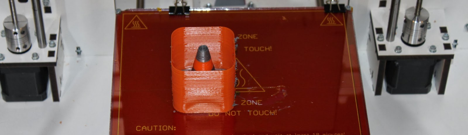
Thats it! - time for a test print:


The fan has been left off up to this point to make calibration easier - it is now time to fit it.

Most people are opting for the acrylic cabinet which can also be fitted at this stage and goes together in a similar fashion to the frame with M3 screws and square nuts. Fitting it does not disturb the printer calibration:


The entire assembly and calibration process is described in more detail in the manual supplied with the printer kits.

I hope that helps to show what goes into the setup and calibration of the printer following assembly.