Showing posts with label Thermal testing. Show all posts

Wednesday, 5 April 2017

DuetWifi - Updated Thermal Testing

During the prototype development of the DuetWifi we carried out extensive thermal testing to validate the thermal characteristics of the PCB design. The two areas we looked at in detail were the TMC2660 stepper drivers and the high current heated bed MOSFET and associated traces and connectors. The results of this thermal testing allowed us to confidently set the stepper driver current to 2.0A in firmware and recommend a maximum heated bed current of 15A.

Now the DuetWifi has been in production for over 7 months, we have much more information about the performance of the board in the real world. This combined with updated the thermal testing (thanks again to Andy Hingston) has allowed us to make the following changes:

  • increased the recommended maximum heated bed current to 18A 
  • increased the stepper driver current limit will shortly be raised in firmware to 2.4A.
Notes: 

  • this is for production (blue) DuetWifi and upcoming DuetEthernet boards, not for the prototype (white) DuetWifis.
  • If setting stepper driver current higher than 2A ensure there is a fan blowing across the back of the Duet or Duex board.
  • When first using stepper driver currents higher than 2A use M122 to check for over temperature warnings. Future versions of the firmware will have additional functionality to reduce stepper drivers power intelligently if an over temperature warning occurs.


We also took the opportunity to test the Duex5 stepper drivers, these perform better than those on the DuetWifi as they have even more on-board heat sinking. There is more details on the testing results, and caveats, below.


DuetWifi Stepper Testing : 2.5A Half Step Hold*

DuetWifi Thermal Test 2.5A Half Step Hold - 123.3C - Front View
*See the previous thermal testing blog post for an explanation.

Duex5 Stepper Testing : 2.5A Half Step Hold


Duex5 Thermal Test 2.5A Half Step Hold - 102.3C - Front View

DuetWifi Heated Bed MOSFET Testing : 20A soak test


DuetWifi Thermal Test Heated Bed 20A 86.7C - Front View

DuetWifi Thermal Test Heated Bed 20A 77.1C - Front View
The tests were completed under the following conditions:
  • Board under test: DuetWifi v1.01, Duex5 V0.7
  • Ambient Temperature: 25-27C
  • Soak Time: 20 minutes


Friday, 15 July 2016

DuetWifi Thermal Testing

The DuetWifi is our new advanced 3d printing electronics board based on the Duet 0.8.5 but completely redesigned with David Crocker (DC42 on the reprap forums). We are currently running a pre-order which is due to end 17 Jul 2016 with the first boards delivered in the first week of August. We have also had a batch of pre-production beta boards made which are with beta testers right now. We put one of the boards through thermal testing by Andy Hingston (who was part of the Duet 0.6 design team). This blog post will deal with the thermal testing, I have future posts planned to detail the hardware design of the DuetWifi.

The main concern for heat generation on the board are the stepper driver chips. The TMC2660s are rated to 2.8A RMS, however we have limited them in firmware to 2A for now. What our testing has shown is that the TMCs drivers, coupled with the board design mean these drivers will run cool in most "normal" desktop size 3d printers (~1A motor current) and have the capacity to scale for significantly larger printers comfortably (~2A motor current).

In order to do a comprehensive test we decided to test the TMCs with 1A, 1.5A and 2A (RMS) of stepper motor current in three conditions:

  1. With the motors held in a "half step": in this condition there is 100% of the current flowing through half of the stepper driver with 0% through the other half.
  2. With the motors held in a "full step": in this condition there is 1/Sqrt(2) of the current ~70.7% of the maximum current flowing through both halves of the driver.
  3. In a normal microstepping mode with a step frequency of 8000 steps/min at 16 microsteps, interpolated by the drivers to 256 microsteps.
In all cases we allowed the temperature to stabilise for 20 mins from an ambient temperature of ~25C

The results: in summary the drivers and heatsinking design on the board have performed really well. At 2A RMS in the "half step" condition (the worst case) we saw the temperature rise to 87.7C (a 62.7C rise from ambient). In the actual use case of the normal stepping at 2A it was a rise to 71C (a 46C rise from ambient). All these tests were performed powering X,Y and Z drivers on the board at the same time so that the Y driver had hot drivers on either side of it. We expected it to get the hottest but actually Z was generally the hottest by about a degree indicating the importance of the PCB to dissipate the heat.

The thermal camera output is below; click on the pictures for larger images.

1A Half Step hold
DuetWifi Thermal Test 1A Half Step Hold - 48.7C

1.5A Half Step hold
DuetWifi Thermal Test 1.5A Half Step Hold - 62.1C

2A Half Step hold
DuetWifi Thermal Test 2A Half Step Hold - 87.7C - Front View
This view of the back of the board shows just how effective the heatsinking on the back layer is.
DuetWifi Thermal Test 2A Half Step Hold - 71.0C - Back View


1A Full Step hold
DuetWifi Thermal Test 1A Full Step Hold - 51.0C

1.5A Full Step hold
DuetWifi Thermal Test 1.5A Full Step Hold - 62.1C

2A Full Step hold
DuetWifi Thermal Test 2A Full Step Hold - 79.8C


1A Normal Stepping
DuetWifi Thermal Test 1A Normal Stepping - 41.8C

1.5A Normal Stepping

DuetWifi Thermal Test 1.5A Normal Stepping - 55.5C

2A Normal Stepping

DuetWifi Thermal Test 2A Normal Stepping - 71.0C

The other area of interest as far as power dissipation on the bard was the heated bed MOSFET and associated power traces. We wanted to carry at least 15A so I increased the width of the trace and doubled it up (both front and back). With 15A on constantly we saw a stable temperature of 88.5C at the hottest point.

DuetWifi Thermal Test 15A Bed MOSFET - 85.3C on Front power (-) trace, 81.9C on MOSFET

DuetWifi Thermal Test 15A Bed MOSFET - 88.5C on Back power (+) trace

Monday, 30 December 2013

Duet FET, PSU and Stepper Driver Testing

This blog post is primarily a cut and paste from notes made during the testing of the Duet v0.3 (note the current version is 0.6). I have uploaded the design files for version 0.3 onto the archive area of the github project so the differences between the design tested in these pictures and the current design can be seen.

Normally I would try and get more detail into the post about the design decisions but that will have to wait until a later post.

FETs Testing


FETs are on by default when 3.3V regulator is disconnected as Vgs = 5V (same as when MCU turns FETs on), so software not required. (Note this setup has been replaced in version 0.6 with FETs off by default).

Tested with 10A load gives Vds = 32mV - therefore dissipating 0.32W


32mV at 10A = 3.2mOhm on resistance. As expected from datasheet.Temp measured at ~40C with thermal camera (ambient ~23C):


Track adjacent to FET (carrying input power) got marginally hotter, though nothing to worry about particularly but aim to increase track width on Duet v0.4.

A 20A load would give 1.28W dissipation. i.e. 4 times as much as 10A, therefore expect 50-60C temp rise on FET from ambient. FET rated to 175C.

PSU Testing

Perfectly happy at low loads (<750mA) (note the Arduino Due Power supply only dives a total of 800mA). 12-24V in, 4.98V out. Voltage ripple = ~30mVpk-pk (DC-20MHZ) See scope plot below:


Marginally unstable with 1A or greater load and Vin >16V.
Voltage ripple = ~100mV (DC-20MHz). See scope plot below:


At 1A load, PWM IC temp = ~40C:


At 1.5A load, PWM IC temp = ~60C:


Further testing on 20/06/13:

Inductor L1 swapped from 22uH to 8.2uH. Tested 12V to 24V input and 0A to 1.5A output load.


12V input, 1.5A load, voltage ripple+noise = ~60mVpk-pk (DC-20MHZ) See scope plot below:


24V input, 1.5A load, voltage ripple+noise = ~90mVpk-pk (DC-20MHZ) See scope plot below:

Stepper Motor Testing

Initial testing completed using stepper.ino sketch. Timings changed to 10,000 for CW and 25,000 for CCW steps. An unloaded motor was run for 30mins with these step rates and then a thermal image was taken of Duet board. See below:


The three hot-spots seen in the image are the 3.3V regulator, the MCU and the stepper driver IC. All three showing temps of around 45C.

Note: Other random colourful spots are reflections off shiny surfaces - e.g. button switches and SD card slot. 

Afterward

The main point of posting this now is to inform the discussion on the RepRap forums about potential improvements to the Powersupply:

http://forums.reprap.org/read.php?340,285306

A great example of the benefits of releasing an open source design - really high quality feedback!


Thursday, 15 August 2013

Stepper Driver Thermal Testing

As mentioned in my previous post I am working on an improvement on the original Stepstick design. I arranged for a test to be carried out on the original Pololu (green, A4988), a Pololu "Black Edition" (A4988 on a 4 layer board), A4982 Stepstick (bought from eBay, assumed thin copper and 2 layer board), and the prototype of my new design, provisionally called the "Ice Blue Stepstick". Each one was subjected to the same current and stepped through the same sequence with thermal images to see how efficient they are at heat dissipation. The result: the new design is more than 10% better than the Pololu Black Edition!

The test results in full are below:


Comparison of Stepper Driver boards

Thermal imaging tests carried out for Think3DPrint3D.

Set up
Thermal testing of various different stepper driver “shields” carried out using a test sketch.
       Sketch set to run 10,000 x 100us steps clockwise followed by 15,000 x 50us steps counterclockwise, with a 200ms delay between direction changes.
       Drivers were set to 1/16th microstepping with the current limit set to 1.25A.
       Drivers were run for 5 minutes and a thermal image of the driver shield was taken at the end of that time, while the motor was still running.
       No additional heatsinking was added to the stepper driver ICs.
       The motors were all the same model, unloaded, 4.4kg/cm NEMA 17 motors used on many 3d printers.

Drivers tested were as follows:
1.    Stepstick - A4982 - TSSOP IC - 2 Layer PCB - 1oz copper 
2.    Pololu 1182 - A4988 - QFN IC - 2 Layer PCB - 2oz copper
3.    Pololu 2128 - A4988 - QFN IC - 4 Layer PCB - 2oz copper
4.    T3P3 Ice Blue Stepstick - A4982 - TSSOP IC - 4 Layer PCB - 2oz copper
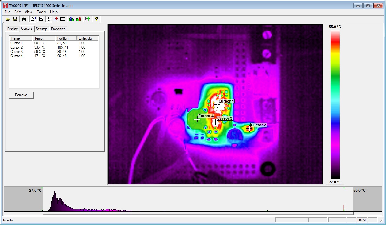
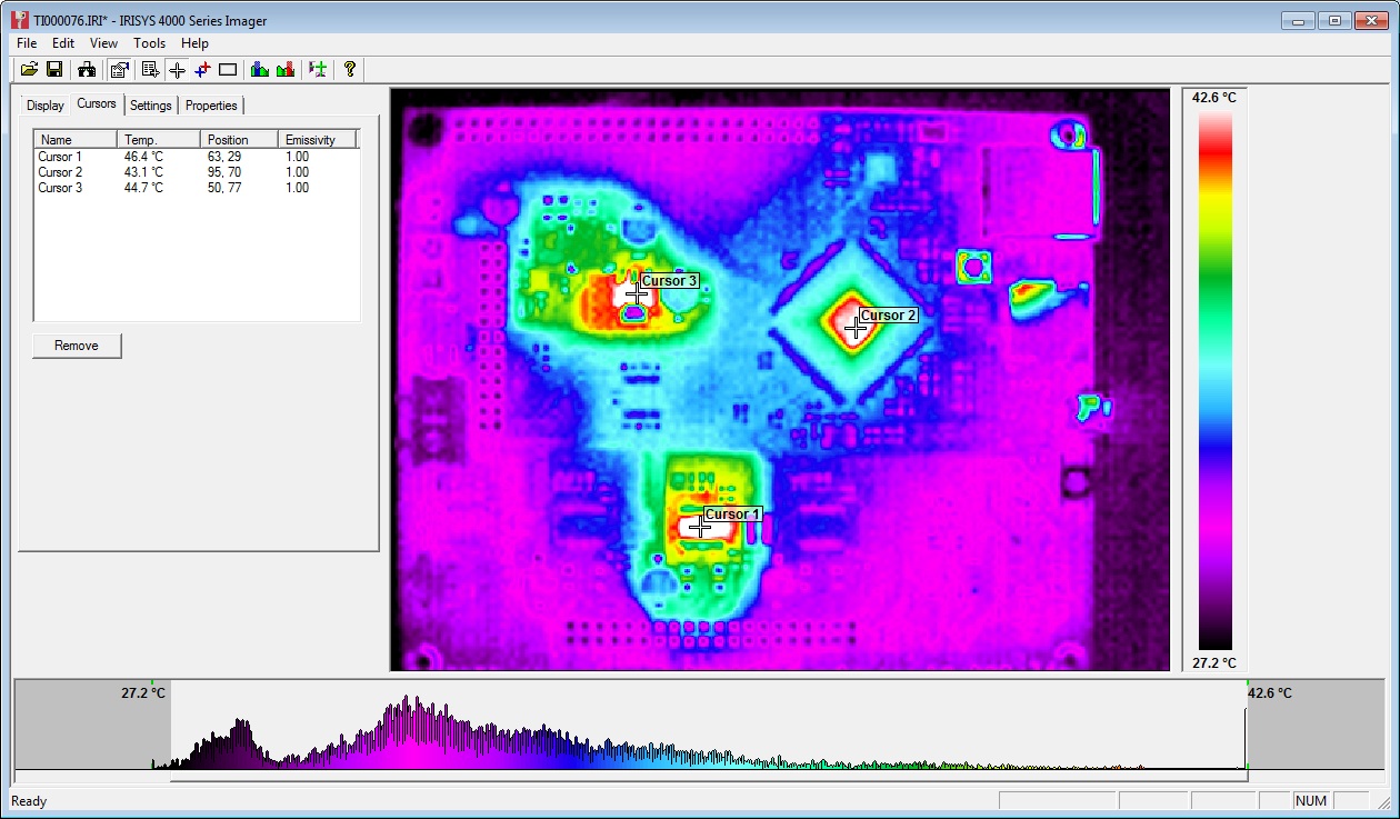
Results

1.     Stepstick - A4982 - Max temp = 133.8C, thermal shutdown was occurring during the test. 


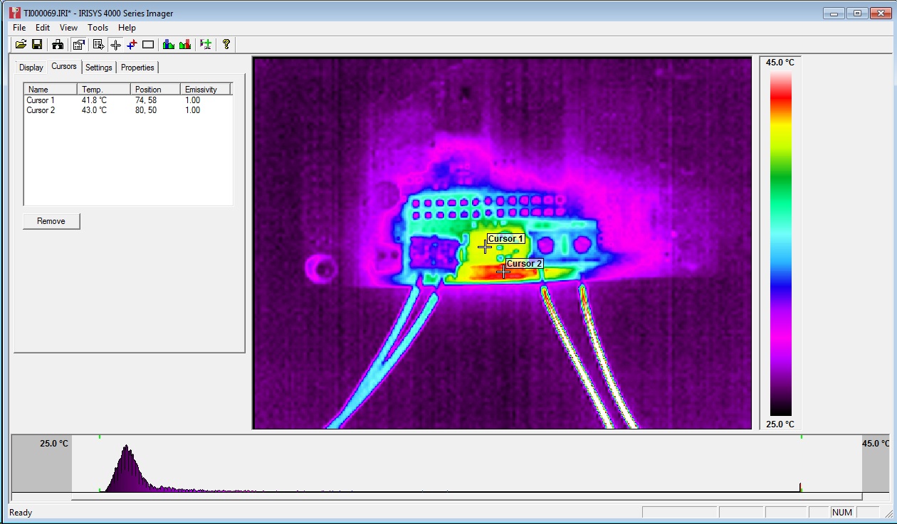
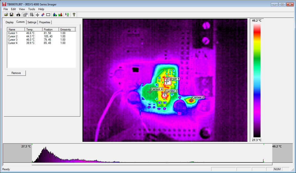
2.     Pololu Green - A4988 - 2 Layer - Max temp = 110.6C


3.     Pololu Black - A4988 - 4 Layer - Max temp = 88.8C


4.     T3P3  Stepstick – A4982 – Max temp = 79.0C


Discussion

The old Stepstick tested as number 1 as almost certainly built using 1Oz rather than 2Oz copper and is dual layered rather than 4 layered hence the worst thermal performance. In addition the supplier has not published their design changes from the original Stepstick so it is hard to see how thermally efficient (or not!) that design is.

Pololu claim a 20% improvement in thermal efficiency between the 2oz 2 layer board (no. 2) and the 2oz 4 layer board (no. 3) for the A4988 which these test results support.

The "Ice-Blue" Stepstick which is similar to the A4988 4-layer Black Edition Pololu runs slightly cooler than the Pololu, probably due to the larger heat dissipation area of the A4982 TSSOP package.

The 1.25A test current is higher than that used for most RepRap type 3D printers and heatsinking & a cooling fan would be recommended to further reduce the temperatures, even for the Black Pololu/Ice Blue Stepstick.