Having seen the PanelMax LCD and Encoder for RAMPS, I wanted to get a similar setup working on Sanguinololu. the first step was to get an ATmega 1284P working and load Marlin firmware which supports this sort of setup with minimal changes.
Wiring and Testing
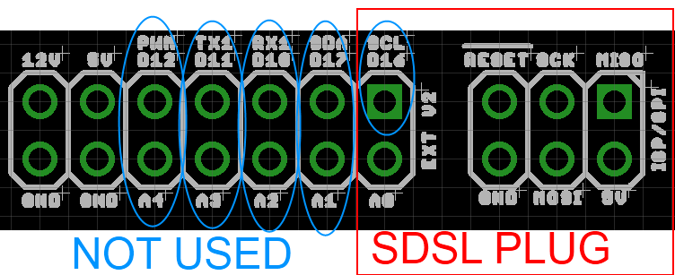
I intended to keep using the SDSL card reader (not much point in having a screen if you have to have you computer plugged in) which left very few pins unused on the microprocessor. Conveniently these are all together on the expansion header:
For the LCD;
RS "PWM" Digital pin 4
ENABLE "SDA" Digital Pin 17
D4 "A1" Digital Pin 30
D5 "A2" Digital Pin 29
D6 "A3" Digital Pin 28
D7 "A4" Digital Pin 27
For the Encoder;
EN1 "RX1" Digital Pin 10 (must be a hardware interrupt pin)
EN2 "TX1" Digital Pin 11 (must be hardware interrupt pin)
SW1 "SCL" Digital Pin 16 (Click switch)
Adds up to 9, just enough!

I connected the circuit up (quickly, I was impatient!) as shown in the Schematic. Note that the connection marked SCL on the Sanguinololu expansion header is plugged onto by the SDSL plug, but not used by the SDSL, I have connected onto this pin where it comes out of the plug as it is needed for the push switch in the encoder. The two variable resistors as 5K as that is what I had to hand, the one for the LCD brightness (R1) is set to around 1K, the one for the LCD contrast (R2) is set to around 4.5K Ohms.
After connecting it up I loaded the Arduino 0023 IDE, and modified the "Hello world" example program from the LiquidCrystal library. The only modifications made were to the pin assignments;
LiquidCrystal lcd(4, 17, 30, 29, 28, 27);
and define it as a 20x4 LCD
lcd.begin(20, 4);

So first step accomplished: the Sanguinololu talking to an LCD Screen.
Next I messed around with some of the examples shown on the Arduino rotary encoder page and ended up with a bit of a hybrid one that allows you to move the cursor around the screen with the encoder, with an arrow to show which way its going. Clicking the switch on the encoder resets it to the middle.
 |
| Left |
 |
| Right |
Working with Marlin
Using the modifications on tommyc's blog as a starting point I checked and modified the Marlin Configuration.h, Configuration_adv.h and pins.h as shown below:
Configuration.h
Line 34:
#define MOTHERBOARD 62
Line 190-205:
#define EEPROM_SETTINGS
//to disable EEPROM Serial.....
// please keep turned on if you can.
#define EEPROM_CHITCHAT
//LCD and SD support
//#define ULTRA_LCD //general lcd support, also 16x2
//#define SDSUPPORT // Enable SD Card Support in Hardware Console
#define ULTIPANEL
#ifdef ULTIPANEL
#define NEWPANEL //enable this if you have a clicencoder panel
#define SDSUPPORT
#define ULTRA_LCD
#define LCD_WIDTH 20
#define LCD_HEIGHT 4
Configuration_adv.h
Line 163:
//#define SDCARDDETECTINVERTED
pins.h, making sure to be within the sanguinololu pin definition part of the file. For my pins.h this was lines 557 - 657. I added the following 34 lines, copied from the RAMPS section of the pins.h
#ifdef ULTRA_LCD
#ifdef NEWPANEL
//we have no buzzer installed
#define BEEPER -1
//LCD Pins
#define LCD_PINS_RS 4
#define LCD_PINS_ENABLE 17
#define LCD_PINS_D4 30
#define LCD_PINS_D5 29
#define LCD_PINS_D6 28
#define LCD_PINS_D7 27
//The encoder and click button
#define BTN_EN1 10 //must be a hardware interrupt pin
#define BTN_EN2 11 //must be hardware interrupt pin
#define BTN_ENC 16 //the switch
//not connected to a pin
#define SDCARDDETECT -1
//from the same bit in the RAMPS Newpanel define
//encoder rotation values
#define encrot0 0
#define encrot1 2
#define encrot2 3
#define encrot3 1
#define BLEN_C 2
#define BLEN_B 1
#define BLEN_A 0
#endif //Newpanel
#endif //Ultipanel
Once these changes had been made, Marlin compiled to be 80k+ so definitely too big to go on the 644P. After upload the Printer status display came up:

And rotary encoder worked fine to navigate the menu system...

I selected a random GCODE file from the SD card and started printing it (or rather the Sanguinololu controller started processing the GCODE, its not connected to anything other than a 5k pot to simulate the hotend thermistor)

Once the printing starts you can use the encoder to "tune" the speed of the printer, its currently set to 200% below:

The pseudo print continued without issues. The next step will be to tidy up the wiring and get it connected up to a live printer!