Printer Overview
The Mendel90 Lasercut is a RepRap printer: there is much more information about RepRaps in general on the wiki but in summary it is a printer which can print the plastic parts that go into its assembly along with many other interesting and useful things. To get an idea of what people are using RepRap-style printers for, a good place to look is Thingiverse. Most CAD and 3D design software can export ".stl" files which the printing software uses to generate print instructions. The printer works by laying down layers of plastic, one on top of the other, to build up an object, in a process called fused filament fabrication.
The Mendel90 lasercut has a build area of 200mm x 200mm x 200mm and comes with a single 0.4 mm extruder nozzle which can reliably print layers as thin as 0.1mm. With a smaller extruder nozzle it can reliably print as low as 0.02mm.
Looking at the printer from the front, the Mendel90 LC axis are X left and right, Y backwards and forward and Z up and down. The print head is in the 0,0,0 position when it is fully to the left (X=0), the heatbed is fully to the back (Y=0) and it is just touching the surface of the glass on the heatbed (Z=0). The "homed" or parked printhead position is at 200,200,200.

The main components of each axis are:


The frame parts are the base, portal, buttresses, back-top and extruder "sandwich" (for potential future developments)


The electronics are mounted at the right buttress along with the power supply unit. They support the addition of other types of electronics in future upgrades.
General points
- The printer is made up of sub-assemblies which need to be completed before each major part of the printer is assembled. The sub assemblies can, in general, be worked on in parallel if more than one person is assembling the printer, reducing the build time.
- The printer design in regularly updated, so refer to the manual that is distributed with your printer for the most up to date instructions.
Tools

- Spanners/sockets: 5.5mm, 7mm & 13mm.
- Allen keys: 1.5mm, 2mm, 2.5mm, 3mm
- PZ 1 Pozidriv screw driver and 2mm slotted screwdriver
- Digital callipers
- Lithium/PTFE grease, glass cleaner (acetone recommended).
- Multi-meter (optional)
X axis sub-assemblies
The X Idler and Motor brackets are the interface between the X axis and the Z axis and are the most complex sub-assemblies.


X Idler


X Motor
The X Carriage runs on the X rods between each motor end, and the extruder and fan are attached to it


X Carriage


Extruder Fan


Extruder
Y axis sub-assemblies
In comparison the Y axis and its sub assemblies are simpler.

Y Idler


Y Motor


Y Carriage
Z axis sub-assemblies


Z Endstop


Z Motor Boxes


Z Top Brackets
Frame Assembly
Once the sub assemblies are done the frame slots together using square captive nuts and M3 fasteners.

First the buttresses, back-top and extruder "sandwich" are assembled:


Then the portal and motor boxes are added:


Finally the base and the aluminium channels are fixed on:


The assembled frame:

Y Axis Assembly
The Y Axis runs along the base and is the first axis to be assembled onto the frame, starting with the bar clamps

Then the motor, rods and the Y axis assembly are added. This assembly sequence allows for the belt to be a pre-set length and for the rods clamps to be tightened with the axis in place to ensure it runs true

A heat shield is added before the bed is fixed above it.


Z and X Axis Assembly
As noted earlier, the X Axis idler and motor brackets are the interface between the Z and X axis and these axes are assembled together.
First the Z top brackets are fitted, then the smooth rod is fed down through the X axis idler and motor brackets.The X rods are slid through the X idler and the X carriage.

The Z axis screws are then added and the wiring tidied up,


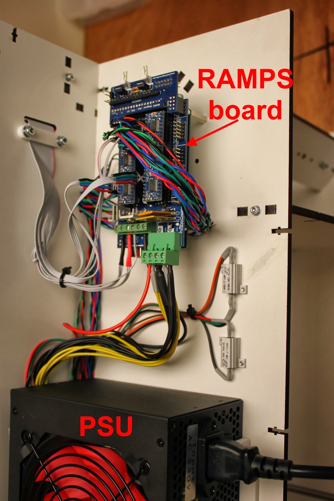
Electronics
By this point all the wires from each motor, endstop and the hotend and heatbed are routed through to the back right of the machine ready for the power supply and printer controller board to be fitted.

The Arduino board and the RAMPS are mounted on the hex pillar standoff before the wiring is plugged in.


Update: The source files on github for the Mendel90 Lasercut have now been modified to include changes to the X Idler and X motor brackets that makes them easier to print and more robust. This is one of a number of changes that have been incorporated from Nophead's latest update to the design.
Hi guys,
ReplyDeleteNice work. One or two small questions...
Why did you need to place a tripple layer bracing piece to the top rear between the two buttresses? Is it adding structural rigidity, or does it have some other function? You have me guessing!
And why on earth did you call the piece an "extruder sandwich"? :-)
Tks,
NumberSix
Hi NumberSix
Delete"Spoilers!"
The extruder "sandwich" is designed to take up to 5 RepRapPro style mini bowden extruders - allowing for multi-colour and multi-material printing. Because this would be a pain to add it later it is designed in from the beginning. I went with the triple layer because I wanted more rigidity than a single layer and the triple layer allowed the fastening scheme to be easier. A double layer would have had two slots joined together which had the potential to be aligned poorly.
The new X carriage design is intended to be modular to support addition of heads as required, but I have still got to do quite a bit of work to confirm the wiring scheme (stay with the M90 ribbon cable and D type connector which I like or not, etc?).
There will be a lot more to come in the next few months and the intention is that all the Mendel90 Lasercut kits that are sold now will have a supported upgrade path to multiple extruders.
Cheers
Tony
Hi Tony,
ReplyDeleteSounds like you have some great plans there, and the M90 platform is certainly an excellent chassis to base it all on. I look forward to seeing how it evolves.
Thanks for sharing. Hope I didn't force you to share plans too early! :-)
NumberSix
Hi Tony
ReplyDeletewe met at tct show in Birmingham , we realy like your printer and are more than interested,
you also wanted to improve your nozzle, we spoke about making you a stainless one.
lance
Hi Lance
DeleteGreat to hear from you again, I remember the conversation. If you check out the web shop linked at the top of the blog all our contact details are there. Among other things my ongoing quest for the ultimate hot end design is ongoing, I have recently been playing with a number of different designs so would be very happy to discuss "machinability" with you.
This comment has been removed by the author.
ReplyDeleteThis comment has been removed by the author.
ReplyDeletethe dxf you are looking for is this one:
Deletehttps://github.com/T3P3/Mendel90/blob/LaserCut/lasercut/sheets/T3P3_LC_M90_v1.0.dxf
it should have every part in it.
Cheers
Tony
Hi Tony I have a problem using your fantastic dxf files, I can't open them after downloading are they corrupt? - please can you check this?
DeleteManfred
Hi Manfred, are you using the files from the github? The DXFs open fine in inkscape (they are direct OpenSCAD exports) are you downloading the hole project as a zip file?
DeleteHi,
ReplyDelete(Daft question alert) Just out of interest what is the frame material made of? Is it painted MDF of Dibond?
Thanks in advance,
Tom
Hey Tom
DeleteIts made of Melamine faced MDF. This much harder wearing than regular MDF and allows for the fixing method used in this design. Dibond is also a great material and what Nohead uses in his kits but it would not work well using this fixing method.
The full BOM is here:
http://www.think3dprint3d.com/3D-Printer-Kits/Mendel90-Lasercut-kit/#tab-product-tab4
which shows what everything is in the kit.
Cheers
Tony
Thanks for quick reply!
DeleteDo you know of problems with moisture warping of the MDF?
I believe the dibond was originally selected to avoid this issue. (as well as mass for transportation)
Cheers;
Tom
Hey Tom
DeleteUn protected MDF can moisture warp - our original MDF Mendel90s were all varnished for this reason.
The Melamine coating and laser cut edges minimised the problem - I have noticed no warping at all, even on the v0.1 prototype (still going strong after over a year). That said we use them in a relatively dry environment (worst case is an unheated garage) and also they are used frequently! that compired with the enclosure means they keep dry.
If you were going to make one to use in a very damp/humid environment then Dibond would be much better, but there are other issues as weel to consider such as the choice of metal parts to avoid corrosion.
Cheers
Tony
Hi Tony
ReplyDeletehave had a slight problem with our 3 d printer and you dad Roland said to send part back,,
which we have done but I cant seem to get in contact with him now and were a bit desperate as we have a few things to print.
Kindest regards
Lance
Hi Lance
DeletePlease email him on think3dprint3d@gmail.com he will get straight back to you!
Cheers
Tony