The version of Marlin this is based on is the current (as at 15/05/13) Marlin_v1 version, modified slightly to incorporate the Think3dPrint3d Panelolu2. There are various different Marlin versions:
EricZalm master version
Think3DPrint3D version
RepRapPro version
Nophead version
This post is aimed at helping users of RepRapPro Marlin and Nophead's Marlin migrate their configurations to T3P3 Marlin in order to use the Panelolu2; however it may be helpful to others who are setting up their configuration.h for the first time.
Refer to the working/default Configuration.h from your current setup if you have one and use that as a guide to what settings to put at each stage - if in doubt use the default setting from your printer manufacturer as a start point.
Note: I do not cover every setting, just the main ones to get up and printing.
Environment
The T3P3 version of Marlin is only tested on Arduino-0023 and on the following electronics boards:Sanguinololu 1.2, and 1.3a
Melzi
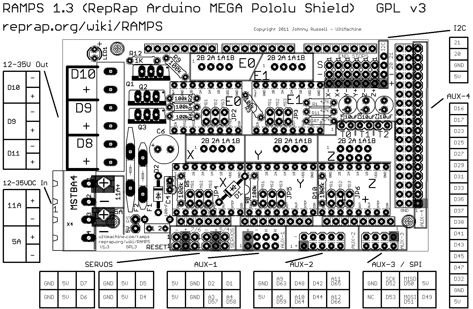
RAMPS 1.3 and 1.4
Printrboard
First open Configuration.h in your favourite text editor or the Arduino IDE (it is located in <Marlin Folder>\Marlin\Configuration.h)

I will refer to the line number in the version of the T3P3 firmware available today. This will change over time and get out of date but it will be a good start and it should be fairly obvious which line I am referring to. You can see the line number on the bottom left of the Arduino IDE screen - in the shot above the cursor is on line 12.
Add an Author/Version
Line 12
#define STRING_CONFIG_H_AUTHOR "(<something useful here>)" //Who made the changes.
This is helpful to confirm with a glance which version of your configuration.h is loaded on your hardware:

Baudrate
Line 20
// This determines the communication speed of the printer
#define BAUDRATE 250000
//#define BAUDRATE 115200
Keep this on the faster setting unless you have a need to use a slower setting. Make sure you select the same baudrate in Pronterface (or your control software) as you have set here when you connect.
Motherboard
Line 51
#define MOTHERBOARD 7
As the comment above this line shows there are many supported electronics motherboards. Make sure you chose the right version for your electronics (for example 63 for Melzi, 33 for RAMPS 1.3/1.4 with 1 extruder, 34 for RAMPS 1.3/1.4 with 2 extruders etc).
Temperature Measurement
Line 90
#define TEMP_SENSOR_0 1
#define TEMP_SENSOR_1 0
#define TEMP_SENSOR_2 0
#define TEMP_SENSOR_BED 1
If you have a RepRapPro printer, their custom version of Marlin does not use a pre-calculated thermistor lookup table but computes the values directly. I have incorporated this into the latest T3P3 version on Marlin as described in my previous blog post. My copy is rather untested so use with caution. Even though on-the-fly calculation is now available, I recommend using tables. Nophead's blog describes the theory behind the table calculations and the "createTemperatureLookupMarlin.py" script in the Marlin folder allows for the calculation of an accurate table for your thermistor and temperature range of interest.
If you want to use the calculated thermistor values then:
Line 97
//use RepRapPro Algebraic Temperature calculation rather than
//the tables - still experimental in this version of Marlin.
#define ALGEBRA_TEMP
Line 104 onwards
Choose the serial resistor for your electronics (4700 is standard)
#define SERIAL_R 4700
//#define SERIAL_R 10000
Choose your thermistor Beta values (from the data sheet, ask your supplier) and value at 25C (100K thermistor is 100000, 10K is 10000)
// EPCOS B57560G104F (the standard 100K one)
#define E_BETA 4036.0
#define E_NTC 100000.0
#define BED_BETA 4036.0
#define BED_NTC 100000.0
Other standard thermistor types that RepRapPro uses are already in configuration.h, commented out. If you change to these types then comment out the lines referring to the EPCOS and uncomment the lines for the thermistor values that match yours. For example to use the latest RepRapPro thermistor values comment out:
// EPCOS B57560G104F (the standard 100K one)
//#define E_BETA 4036.0
//#define E_NTC 100000.0
//#define BED_BETA 4036.0
//#define BED_NTC 100000.0
and uncomment
// RS 198-961#define E_BETA 3960.0#define E_NTC 100000.0
// Rapid 61-0446 ; Semitec 103GT-2 All RepRapPRo Mendels and Thermistors shipped after 1/4/13#define BED_BETA 4126.0#define BED_NTC 10000.0
Temperature at Print Start
Line 137#define TEMP_RESIDENCY_TIME 10 // (seconds)
#define TEMP_HYSTERESIS 3 // (degC) range of +/- temperatures considered "close" to the target one
#define TEMP_WINDOW 1 // (degC) Window around target to start the residency timer x degC early.
These allow you to control how close to the exact set temperature the thermistor reading needs to be to begin extruding. The defaults work OK, however to get a quicker start, I change my TEMP_RESIDENCY_TIME to "5" and TEMP_WINDOW to "2".
Max and Min Temperatures
The printer will give an error if the temperatures are outside of these values. I find that in a cold garage in winter the MIN_TEMPs need to be "1" rather than "5". Don't comment out or set to 0 or else the hotend could overheat if the thermistor is disconnected or breaks.
Line 144-155
#define HEATER_0_MINTEMP 1
....
#define HEATER_0_MAXTEMP 275
....
PID Temperature control
In order to get more stable extruder temperature control the use of PID control is recommended. To enable it ensure PIDTEMP is uncommented.
Line 164
#define PIDTEMP
You need to set the PID constants specific to your hotend. See Wikipedia theory on PID control if interested (not required to make this work):-
Line 178 onwards
#define DEFAULT_Kp 22.2
#define DEFAULT_Ki 1.08
#define DEFAULT_Kd 114
By far the easiest way to calculate these is to use PID autotune once your firmware is uploaded to your printer. This function experiments with the reaction of your hotend and calculates the best PID values. For more detail of PID autotune check this wiki entry. Once you have the values you can save them to EEPROM (see the section later in this guide about enabling EEPROM) or you can replace the values in the firmware (at line 178 as shown above) and re-upload your firmware.
You can use PID on the heated bed in a similar manner but I don't find it necessary. To do so uncomment PID_TEMP_BED:
Line 203
#define PIDTEMPBED
and define the constants for your bed. It is best to use PID autotune for this as well, choosing a different target temperature, as suggested in the Marlin comment:
"FIND YOUR OWN: "M303 E-1 C8 S90" to run autotune on the bed at 90 degreesC for 8 cycles."
Line 216
#define DEFAULT_bedKp 10.00
#define DEFAULT_bedKi .023
#define DEFAULT_bedKd 305.4
Extruder protection
The following lines prevent extrusion when conditions are not right.Line 233
#define PREVENT_DANGEROUS_EXTRUDE
#define PREVENT_LENGTHY_EXTRUDE
Only comment them out to override the effect they have if you have a specific reason for doing so.
Endstops
For Sanguinololu, RAMPS, Melzi and most other common electronics all the endstop pullups should be on - ensure line 248 is uncommented:Line 248
#define ENDSTOPPULLUPS
Generally you want the endstops to trigger when open: this is controlled with the following lines:
Line 270
const bool X_ENDSTOPS_INVERTING = false; // set to true to invert the logic of the endstops.
const bool Y_ENDSTOPS_INVERTING = false; // set to true to invert the logic of the endstops.
const bool Z_ENDSTOPS_INVERTING = false; // set to true to invert the logic of the endstops.
For more information on endstops and why it is generally better to have Normally Closed Endstops have a look at this part of the Reprap wiki and the linked forum post.
Axis direction is controlled by the motor wiring and by these lines:
Line 287
#define INVERT_X_DIR false // for Mendel set to false, for Orca set to true
#define INVERT_Y_DIR false // for Mendel set to true, for Orca set to false
#define INVERT_Z_DIR true // for Mendel set to false, for Orca set to true
Many printers only have 3 endstops, one per axis, so you have to tell the firmware which end to home towards:
Line 296
// Sets direction of endstops when homing; 1=MAX, -1=MIN
#define X_HOME_DIR -1
#define Y_HOME_DIR -1
#define Z_HOME_DIR -1
This combined with the length of the axis sets the dimensions of the printer. It is worth using software endstops to keep the print head within the print area during normal operation:
These need to be set to the correct values for your printer or else you can command the printer to move outside of the area it can cover and potentially cause damage.
Line 300
#define min_software_endstops true //If true, axis won't move to coordinates less than HOME_POS.
#define max_software_endstops true //If true, axis won't move to coordinates greater than the defined lengths below.
// Travel limits after homing
#define X_MAX_POS 205
#define X_MIN_POS 0
#define Y_MAX_POS 205
#define Y_MIN_POS 0
#define Z_MAX_POS 200
#define Z_MIN_POS 0
I find that it is safest with a new printer to set the MAX_POS values to less than the maximum theoretical sizes, then physically check how much more travel is possible and adjust the values upwards if appropriate.
Movement Settings
These settings define how fast your printer's axis move and set the accuracy of moves. In most cases there will be a direct copy from the configuration.h file of your printer supplier. First is the speed the axes move during homing; this is in mm/s and the format X,Y,Z,E. E is 0 because the extruder is not homed.Line 325
#define HOMING_FEEDRATE {50*60, 50*60, 4*60, 0} // set the homing speeds (mm/min)
The next line defines how many steps of the stepper motor are required to move an axis by 1mm. Getting this wrong means the printer axis will not move the right distance. You MUST change the settings from the defaults (unless you actually have an Ultimaker!). Once again the format is X, Y, Z, E. Prusa's calculator is very helpful for calculating the appropriate X, Y and Z values for your stepper motors, belt pitch and pulley teeth. For E, because hobbed bolts all vary slightly, the only way to get the correct value is to start with a reasonable value (e.g. 700 for a Wade's) and calibrate your extruder: RichRap's Slic3r blog provides detailed instructions for doing this.
Line 329
#define DEFAULT_AXIS_STEPS_PER_UNIT {78.7402,78.7402,200.0*8/3,760*1.1} // default steps per unit for ultimaker
Line 330 Onwards
#define DEFAULT_MAX_FEEDRATE {500, 500, 5, 25} // (mm/sec)#define DEFAULT_MAX_ACCELERATION {9000,9000,100,10000} // X, Y, Z, E maximum start speed for accelerated moves. E default values are good for skeinforge 40+, for older versions raise them a lot.
#define DEFAULT_ACCELERATION 3000 // X, Y, Z and E max acceleration in mm/s^2 for printing moves
#define DEFAULT_RETRACT_ACCELERATION 3000 // X, Y, Z and E max acceleration in mm/s^2 for r retracts
// The speed change that does not require acceleration (i.e. the software might assume it can be done instantaneously)
#define DEFAULT_XYJERK 20.0 // (mm/sec)
#define DEFAULT_ZJERK 0.4 // (mm/sec)
#define DEFAULT_EJERK 5.0 // (mm/sec)
EEPROM - Saving Settings without recompiling firmware
When EEPROM is enabled there are three locations where versions of the printer settings are stored.- Hard-coded in Firmware in Configuration.h.
- In the running RAM of the microcontroller - not saved on power down or reset.
- In EEPROM
If EEPROM is enabled the settings are loaded from EEPROM, not from the hard-coded values in Configuration.h. EEPROM settings can be updated using a series of "M" commands. See the G-Code page on the RepRap wiki for a description of all the G and M codes including those for saving and reading from EEPROM.
I recommend enabling EEPROM_SETTINGS and EEPROM_CHITCHAT
Line 356
//define this to enable eeprom support
#define EEPROM_SETTINGS
//to disable EEPROM Serial responses and decrease program space by ~1700 byte: comment this out:
// please keep turned on if you can.
#define EEPROM_CHITCHAT
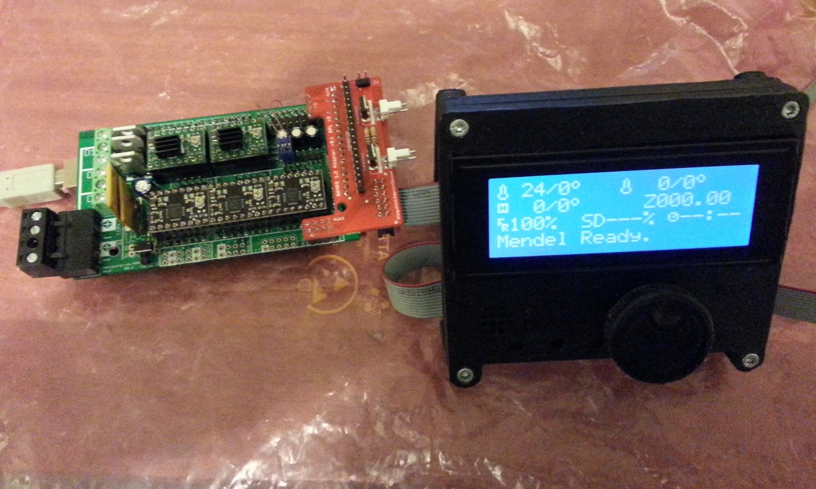
Display Screens - Panelolu2
There are an increasing number of LCD screens supported by Marlin, but this post only covers the Panelolu2. To enable the Panelolu2 uncomment the following line:Line 381
#define PANELOLU2
If you don't like the buzzer making a beep sound then comment out the PAN_BEEP
Line 386
#define PAN_BEEP //comment out to disable buzzer
I recommend that you get your printer working without enabling the Panelolu2 first and then uncomment the #define PANELOLU2 line afterwards. Note that Marlin will hang if the PANELOLU2 is enabled but not connected.