Monday, 7 October 2013

Mendel90 Lasercut - Overview

Thanks for all the interest we have been getting for the new Lasercut Mendel90! This post is to give an overview for those new to 3D printers and answer questions about how easy the M90LC is to assemble. It is not designed to replace the detailed assembly instructions and user manual which are now awaiting final feedback from our beta testers before being published.


Printer Overview


The Mendel90 Lasercut is a RepRap printer: there is much more information about RepRaps in general on the wiki but in summary it is a printer which can print the plastic parts that go into its assembly along with many other interesting and useful things. To get an idea of what people are using RepRap-style printers for, a good place to look is Thingiverse. Most CAD and 3D design software can export ".stl" files which the printing software uses to generate print instructions. The printer works by laying down layers of plastic, one on top of the other, to build up an object, in a process called fused filament fabrication.

The Mendel90 lasercut has a build area of 200mm x 200mm x 200mm and comes with a single 0.4 mm extruder nozzle which can reliably print layers as thin as 0.1mm. With a smaller extruder nozzle it can reliably print as low as 0.02mm.

Looking at the printer from the front, the Mendel90 LC axis are X left and right, Y backwards and forward and Z up and down. The print head is in the 0,0,0 position when it is fully to the left (X=0), the heatbed is fully to the back (Y=0) and it is just touching the surface of the glass on the heatbed (Z=0). The "homed" or parked printhead position is at 200,200,200.


The main components of each axis are:


The frame parts are the base, portal, buttresses, back-top and extruder "sandwich" (for potential future developments) 


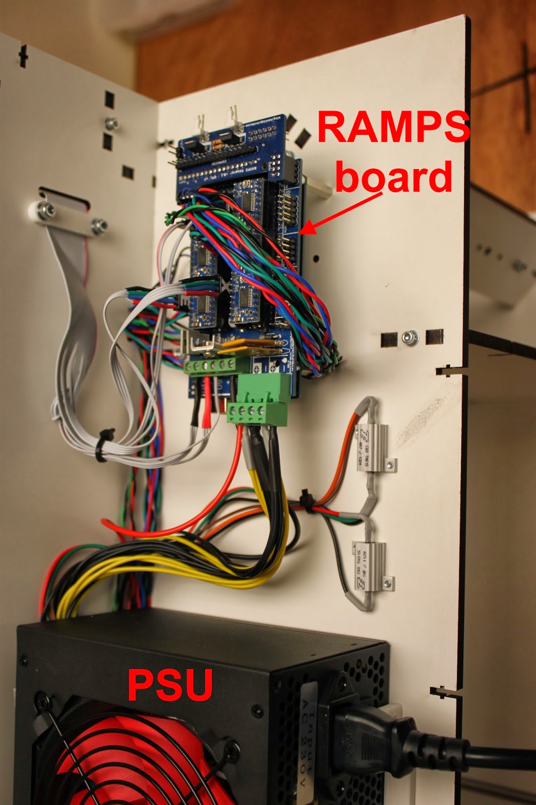
The electronics are mounted at the right buttress along with the power supply unit. They support the addition of other types of electronics in future upgrades.


General points

  • The printer is made up of sub-assemblies which need to be completed before each major part of the printer is assembled. The sub assemblies can, in general, be worked on in parallel if more than one person is assembling the printer, reducing the build time.
  • The printer design in regularly updated, so refer to the manual that is distributed with your printer for the most up to date instructions.
The next section will provide an overview of the assembly process

Wednesday, 2 October 2013

Fun with bee vision colour spaces

I recently spent some time collaborating with Dr Lucas Wilkins, a researcher at the University of Sussex, helping him to visualise the bee vision colour spaces he has been working on. He wanted to be able to show the three dimensional models as a plysical object and 3D printing them is the obvious choice. 

As a 3D printing problem the shapes are interesting because they have no straight lines or flat surfaces, all edges and curves, the "bottom" and "top" are sharp points. After considering printing them with support we tried a simpler option first - slice them in half and then glue them back together with acetone vapor post processing.


A bee vision colour space picture by Dr Wilkins, University of Sussex

After successfully printing the colour spaces we used OpenSCAD to create frames ( in purple PLA in the photo above) by subtracting the colour space shape from the frame for a secure fit.

The details are here in his blog which also gives the links to information about colour spaces and what they are.

All the printing was done on our new Lasercut Mendel90, which will be available from our webstore shortly.

Tuesday, 24 September 2013

Mendel90 Laser Cut - Ready to Print

The Think3dPrint3d Lasercut Mendel90 is ready! After a period of extensive prototyping and beta testing the design is set, and right now multiple versions of this printer are churning out the parts for the initial run of kits.

This is our interpretation of the Mendel90 design by Nophead based around a laser cut frame. It borrows the fixing method from the Lasercut i3 design by Shane Graber and the majority of plastic parts are from the Dibond Mendel90.


A quick orientation around the printer:-

First, the laser cut frame is made from melamine-coated MDF which is much more resistant to knocks then regular MDF and doesn't require any painting or other finishing.


It is very quick to assemble with square nuts and M3 socket cap screws


The build area is 200x200x200mm 


All the wiring comes ready to plug and play in pre-assembled cables or looms so there is no crimping or soldering required at all. The printer comes with a RAMPS controller with 5 "Ice Blue" Stepsticks and the Panelolu 2 controller as standard.


The acrylic enclosure is an optional extra which keeps the heat inside the printer to reduce warp when printing with ABS. It also helps to reduce noise and adds to the professional look of the printer. It uses the same fixing method as the printer frame and can be fixed on quickly and simply without disturbing the printer or calibration.


Overall, the design removes hassle from kit assembly at every turn. The printer can be easily put together in a day, with very little calibration required as all the critical dimensions are set by the laser cut frame. 


Kits will be available shortly (Update: now available from our webstore). We have a couple of components to finish sourcing in bulk and I will do another blog post with a run-down of the assembly process. I also need to tidy up and document the source code for the plastic parts and frame. All the source will be available on our Github before the printer goes on sale.

We are supporting the RepRap stand at the TCT show this year and will have a Mendel90 LC or two on display. The TCT show is free to register for so please do come round and say hello.

Sunday, 22 September 2013

Think3dPrint3d at the TCT show

Come and visit Think3dPrint3d at the TCT show

As RichRap announced on his blog, the RepRap community has a stand at this year's TCT show. The TCT show bills itself as "UK’s definitive and leading Additive Manufacturing, 3D printing and product development technology show" and its certainly going to interesting to see all the different people, companies and technologies out there!

The RepRap Community Hub is being organised by Richard Horne (RichRap) and RepRap Magazine assisted by us, Think3dPrint3d, RepRapPro, RepRap Barcelona, Faberdashery, Active3D and Alessandro Ranellucci who develops Slic3r along with other RepRap enthusiasts.

Think3DPrint3D will have on show our brand new laser cut version of the Mendel90 (more info to follow shortly) along with a preview of some very exciting electronics....

Registration is free, just signup here, we are looking forward to seeing you all there.

Sunday, 8 September 2013

3D printing with Acetal Filament

I recently got some experimental grade acetal filament for testing purposes from Stratum3D. Acetal, or Polyoxymethylene is an engineering plastic with the desirable characteristics of high stiffness and a low co-efficient of friction.

That low co-efficient of friction is where I think it can have a major impact on what can be produced with fused filament 3D printers such as the RepRaps we use. I have visions of moving parts with integral low friction bushings and other surfaces. It is not as low friction as PTFE but has better wear resistance.


The acetal was supplied in 1.75mm filament so the quick change extruder design on the Mendel90 came in handy and I was soon up and printing.


As the picture shows I had to experiment with a number of build surfaces; the advantage of this plastic being slippery in use is a disadvantage when trying to get it to stick to anything! The slight blue tinge to the picture is because it is taken through the acrylic enclosure that I added to our prototype Mendel90, acetal degrades if overheated giving off formaldehyde which you don't want to breathe.


Acetal also takes on moisture readily so I left it in the sealed bag with moisture absorption granules and made a small hole to get the filament out:


Monday, 26 August 2013

Plastic Primer and ABS adhesion to glass bed

(Summary for the busy - plastic primer does not help ABS adhesion to glass heatbeds!, for those interested in more detail -read on)

I have been using "ABS juice" applied to glass sheets on top of a heated bed for a long time now as the only reliable method I have found to get parts to stick well. The one thing that continues to annoy me is having to reapply the coating between prints. The issue is that the film of ABS does not stay stuck to the glass when it's cool, rather it stays stuck to the part printed on it (which makes perfect sense). What I have been looking for is something that will stick really well to the glass and ABS when hot but only to glass when cold.

This is a quick report on Plastic Primer, designed to get "Plastic" style paints to stick to anything, including glass.


It's the best thing I have found so far but it still does not work that well! The problem is the primer sticks really well at low temperatures <50C but becomes tackier the warmer it gets and by the time it's up to ABS bed temperature it does not stick to the glass very well.

The best results I got were after repeated applications of a thin coat of primer, followed by a wipe with ABS juice. The acetone dissolves the primer, making an ABS and primer mixture. This mixture sticks to the bed better than pure ABS Juice and sticks to the object better than pure primer.

Setting the heated bed to the right temperature is also key: too hot and the primer/juice mixture lifts off with the part, too cold and the abs warps and lifts off the bed. In the picture below the marks towards the centre are from when the bed was too hot (100C) - almost clean glass left. The marks towards the front are with the bed too cold (60C).


The parts I was printing are not normally a problem for warping: the Y bearing mounts for a Mendel90. They have rounded corners which helps to reduce warping as well. An example of the warped parts:


Setting the bed to 80C, no fan and first layer 200% extrusion, I managed to get non-warped prints that stuck to the bed:


That said, this method was far from ideal, and appears to only work with parts that are not very prone to warping.

So..... if anyone knows of an adhesive/primer/something else that sticks really well to glass at 20C to >100C, sticks really well to ABS at >100C but does not stick to ABS at room temperature then let me know!

Thursday, 15 August 2013

Stepper Driver Thermal Testing

As mentioned in my previous post I am working on an improvement on the original Stepstick design. I arranged for a test to be carried out on the original Pololu (green, A4988), a Pololu "Black Edition" (A4988 on a 4 layer board), A4982 Stepstick (bought from eBay, assumed thin copper and 2 layer board), and the prototype of my new design, provisionally called the "Ice Blue Stepstick". Each one was subjected to the same current and stepped through the same sequence with thermal images to see how efficient they are at heat dissipation. The result: the new design is more than 10% better than the Pololu Black Edition!

The test results in full are below:


Comparison of Stepper Driver boards

Thermal imaging tests carried out for Think3DPrint3D.

Set up
Thermal testing of various different stepper driver “shields” carried out using a test sketch.
       Sketch set to run 10,000 x 100us steps clockwise followed by 15,000 x 50us steps counterclockwise, with a 200ms delay between direction changes.
       Drivers were set to 1/16th microstepping with the current limit set to 1.25A.
       Drivers were run for 5 minutes and a thermal image of the driver shield was taken at the end of that time, while the motor was still running.
       No additional heatsinking was added to the stepper driver ICs.
       The motors were all the same model, unloaded, 4.4kg/cm NEMA 17 motors used on many 3d printers.

Drivers tested were as follows:
1.    Stepstick - A4982 - TSSOP IC - 2 Layer PCB - 1oz copper 
2.    Pololu 1182 - A4988 - QFN IC - 2 Layer PCB - 2oz copper
3.    Pololu 2128 - A4988 - QFN IC - 4 Layer PCB - 2oz copper
4.    T3P3 Ice Blue Stepstick - A4982 - TSSOP IC - 4 Layer PCB - 2oz copper

Results

1.     Stepstick - A4982 - Max temp = 133.8C, thermal shutdown was occurring during the test. 


2.     Pololu Green - A4988 - 2 Layer - Max temp = 110.6C


3.     Pololu Black - A4988 - 4 Layer - Max temp = 88.8C


4.     T3P3  Stepstick – A4982 – Max temp = 79.0C


Discussion

The old Stepstick tested as number 1 as almost certainly built using 1Oz rather than 2Oz copper and is dual layered rather than 4 layered hence the worst thermal performance. In addition the supplier has not published their design changes from the original Stepstick so it is hard to see how thermally efficient (or not!) that design is.

Pololu claim a 20% improvement in thermal efficiency between the 2oz 2 layer board (no. 2) and the 2oz 4 layer board (no. 3) for the A4988 which these test results support.

The "Ice-Blue" Stepstick which is similar to the A4988 4-layer Black Edition Pololu runs slightly cooler than the Pololu, probably due to the larger heat dissipation area of the A4982 TSSOP package.

The 1.25A test current is higher than that used for most RepRap type 3D printers and heatsinking & a cooling fan would be recommended to further reduce the temperatures, even for the Black Pololu/Ice Blue Stepstick.