Friday, 29 June 2012

Panelolu - In Depth

Update: The Panelolu2 has replaced the Panelolu. It is much quicker to install, has adapter boards to no messing with cables and uses less pins. The blog post with the information is here, it is available to buy in our webshop.


Panelolu is an LCD and rotary encoder with a click button control solution which derives from the PanelMax Prusa by tommyc. It allows control of a 3D printer running Marlin firmware and Sanguinololu or similar electronics directly without having to have a computer connected. Stand-out features are the ability to start and stop prints, control print speed while printing and change many calibration settings - saving these to the memory on the ATmega 1284 (EEPROM) so they are persistent if you turn the printer on and off. Continuing with tommyc's design the panelolu has mounting brackets for the Prusa mendel or other threaded rod based printers. The brackets are separate from the enclosure so they can simply be replaced with a different design for a different mounting solution.


The Panelolu is designed to use as little soldering as possible (if the breadboard comes pre-assembled and the LCD with plugs fitted then no soldering is required at all) and to allow an easy upgrade path. It uses the SDSL card reader, so if you already have one there is no need to get another. Rather than soldering wires directly to the LCD, headers have been fitted so future changes can re-use the LCD simply.

Whats in the case
 What's in the case

The schematic is a little tangled but each wire can be traced from the Sanguinololu - through the 24 way IDC connector and ribbon cable to its final destination in the enclosure. A 22 way IDC connector would have worked fine but they're are hard to find so we use a 24 way and don't plug in pins 23 and 24.


Assembly instructions

Step 1 - Assemble the tools and components

The Panelolu can be assembled with a few basic tools:
  • Allen Key for the M3 socket head fastenings
  • Cross head screw driver for the SDSL and breadboard mounting screws
  • Small needle nose pliers for crimping connectors
  • wire cutters
If you are assembling the breadboard you will also need a soldering iron and solder.

The enclosure is on thingiverse, as a OpenScad file and STL.

The components are as in the picture below:


The rotary encoder is this one, the reset switch and pots are very generic. Most LCD panels come with mounting holes for M2.5 screws, but I prefer to drill these out slightly and use M3, the enclosure has M3 holes but they should work ok with M2.5 if you prefer to use that.

Step 2 - Assemble the breadboard and the LCD connectors.
(if you get them pre-assembled ignore this step and move to step 3!).

UPDATE: We now supply Panelolu kits with circuit boards - the breadboard instructions below are only necessary if you want to source your own components.

Note these instructions are for a the breadboard assembled with the click encoder on the right of the panel as you look at it from the front - If you want it on the left then mirror the layout.


The schematic contains the circuit diagram for the breadboard. It is laid out to minimise the number of jumper wires required - many of the connections can be bridged.


An absolute minimum of 4 rows and 29 columns are needed in order to fit the screw holes in. The components are placed as shown:


and from underneath:


As shown on the left of the picture of the underside the encoder's mounting legs have been bent round to hold it securely to the board.

The picture below shows the different circuits.

To start with make the direct connections for "ENC 1", "CONT", "BRT" and "RST".

Next use small lengths of wire to make the remaining connections. Leave as little excess wire as you are comfortable with, as it will be easier to fit into the housing:
Solid lines are wire, dotted lines solder connections.


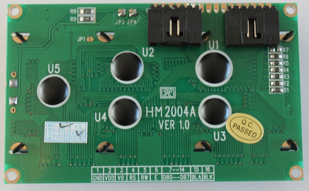
Now do the LCD: Solder the 6 way right angle headers onto the LCD pins 1-6 and 11-16. The picture shows shrouded headers but normal right-angle pin headers are fine.

 
Step 3 - Fit the SDSL and 24 way IDC sockets

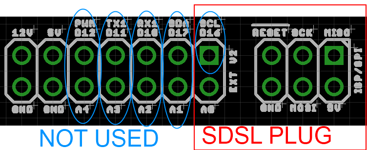
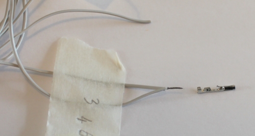
Using the cable numbering from the cable picture, you are connecting wires number 13-22 into the SDSL plug. Note the polarity as shown in the pictures. Ensure you leave at least 10 cm of length on the cable past the plug, as this will make wiring the remaining connections easier.


The easiest way to fit IDC connectors without a proper (and expensive) tool is to use a small vice. Ensure the cable is in square in the connector and the the pressure applied by the vice is even - don’t rush this bit! The back should click into the connector.


The 24 way IDC socket is fitted in the same way; ensure you use pins 1-22 of the socket (a 22 way socket would be even better but hard to find)


Step 4 - Fitting the crimp connectors.
There are three 6-way connectors and a 2 way connector that use crimp terminals. These can be crimped using small needle nose pliers if you don't have a crimping tool. Nophead has an excellent video on how to crimp them.

I found it easiest to identify the wires for each connector from the circuit diagram and the photo below and cut them to length before fitting the pins. Be sure not to make them too short!


The 12V and ground pins on the expansion header are not used by Panelolu but I have left the wires so they can be connected to something else if required. The pieces of wire offcuts in the picture are used to make the connections between the various sockets (as shown in thicker green wires in the schematic near the top of the blog post). Leave these a little longer than the minimum distance to assist with assembly at the end. On some pins you will need to connect two wires to one pin:


Once complete the assembled cable should look like this:


Step 5 - Assemble

It is easiest to first screw on the SDSL socket  and the bread board with the LCD in position, then the strain relief and finally bring the two halves together to plug in the 4 connectors. Although the SDSL itself can be fitted once completely assembled it's easier to fit it at this stage ensuring the orientation is correct.

Close it all up, being careful not to trap any wires. The length of socket setscrews used will depend on the mounting solution. There is a 5th small screw to hold the bottom of the case below the click encoder closed.
I will do a second post about mounting once I have some better pictures of it mounted on a prusa and my Mendel 90 mounting solution sorted.

Firmware

In order to use this you need a 1284P in your Sanguinololu and the Marlin firmware needs the changes that I mentioned in my previous post and have pasted here as well:
Configuration.h
Line 34:
  #define MOTHERBOARD 62 
Line 190-205:
  #define EEPROM_SETTINGS
    //to disable EEPROM Serial.....
    // please keep turned on if you can.
  #define EEPROM_CHITCHAT

  //LCD and SD support
  //#define ULTRA_LCD  //general lcd support, also 16x2
  //#define SDSUPPORT // Enable SD Card Support in Hardware Console

  #define ULTIPANEL
  #ifdef ULTIPANEL
    #define NEWPANEL  //enable this if you have a clicencoder panel
    #define SDSUPPORT
    #define ULTRA_LCD
    #define LCD_WIDTH 20
    #define LCD_HEIGHT 4

Configuration_adv.h
Line 163:
  //#define SDCARDDETECTINVERTED

pins.h, making sure to be within the sanguinololu pin definition part of the file. For my pins.h this was lines 557 - 657. I added the following 34 lines, copied from the RAMPS section of the pins.h

  #ifdef ULTRA_LCD
    #ifdef NEWPANEL
      //we have no buzzer installed
      #define BEEPER -1
      //LCD Pins
      #define LCD_PINS_RS        4
      #define LCD_PINS_ENABLE    17
      #define LCD_PINS_D4        30
      #define LCD_PINS_D5        29
      #define LCD_PINS_D6        28
      #define LCD_PINS_D7        27

      //The encoder and click button
      #define BTN_EN1 11  //must be a hardware interrupt pin
      #define BTN_EN2 10 //must be hardware interrupt pin
      #define BTN_ENC 16  //the switch
      //not connected to a pin
      #define SDCARDDETECT -1
     
      //from the same bit in the RAMPS Newpanel define
      //encoder rotation values
      #define encrot0 0
      #define encrot1 2
      #define encrot2 3
      #define encrot3 1
     
      #define BLEN_C 2
      #define BLEN_B 1
      #define BLEN_A 0
     
    #endif //Newpanel
  #endif //Ultipanel
 
Finally..
Complete kits (less the printed parts) are now available on eMaker and eBay.

Monday, 25 June 2012

Panelolu - an LCD display and control solution for Sanguinololu


As I mentioned in my previous post there is just enough space on the expansion header of the Sanguinololu for a derivative of the excellent PanelMax by tommyc. Tentatively named the “Panelolu” (which sounds like a sort of exotic icecream?), it adds brightness and contrast pots for the LCD and a minimises the reset switch on the front panel. I have adapted the PanelMax Prusa enclosure  and put it as a derivative on Thingiverse - http://www.thingiverse.com/thing:25617. Currently the design is limited for a mounting solution for Prusa and other rod-frame based printers but alternative mounting solutions for other printers will be easy to add - I am working on a Mendel 90 version right now.

  A quick video of the SluloPanel in use on my Mendel90: 


Picture of the assembled unit:

(As you can see from the printed enclosure I am still calibrating my new Mendel90 and struggling with hotends - more of this in another post)

Build instructions will be up soon and we will be supplying kits through eMakershop and ebay once we have put them together. You will need an ATMEGA 1284P, and Marlin firmware with the updates I described in my previous post for this to work. The wiring diagram and STLs for the right handed version are on Thingiverse, I will upload the SCAD and left handed STLs as soon as I have cleaned up the SCAD script - it needs some documentation!

Off to take some pictures of the assembly process and write the build instructions.
Update - more detailed post including build instructions here.

Saturday, 2 June 2012

Sanguinololu, LCD and rotary encoder with switch


Having seen the PanelMax LCD and Encoder for RAMPS, I wanted to get a similar setup working on Sanguinololu. the first step was to get an ATmega 1284P working and load Marlin firmware which supports this sort of setup with minimal changes.

Wiring and Testing


I intended to keep using the SDSL card reader (not much point in having a screen if you have to have you computer plugged in) which left very few pins unused on the microprocessor. Conveniently these are all together on the expansion header:

The image is grabbed from the .brd eagle file - easier to show than on an actual board. There are 9 I/O pins free, one of which is within the SDSL plug footprint but is not used by SDSL. Matching them up to the requirements for a standard 20x4 LCD with a HD47780 interface, and a rotary encoder (with a built in switch) gave;

For the LCD;
RS               "PWM"               Digital pin 4
ENABLE      "SDA"                Digital Pin 17
D4                "A1"                  Digital Pin 30
D5                "A2"                  Digital Pin 29
D6                "A3"                  Digital Pin 28
D7                "A4"                  Digital Pin 27
For the Encoder;
EN1              "RX1"               Digital Pin 10  (must be a hardware interrupt pin)
EN2              "TX1"                Digital Pin 11 (must be hardware interrupt pin)
SW1             "SCL"                Digital Pin 16 (Click switch)

Adds up to 9, just enough!


I connected the circuit up (quickly, I was impatient!) as shown in the Schematic. Note that the connection marked SCL on the Sanguinololu expansion header is plugged onto by the SDSL plug, but not used by the SDSL, I have connected onto this pin where it comes out of the plug as it is needed for the push switch in the encoder. The two variable resistors as 5K as that is what I had to hand, the one for the LCD brightness (R1) is set to around 1K, the one for the LCD contrast (R2) is set to around 4.5K Ohms.

After connecting it up I loaded  the Arduino 0023 IDE, and modified the "Hello world" example program from the LiquidCrystal library. The only modifications made were to the pin assignments;

    LiquidCrystal lcd(4, 17, 30, 29, 28, 27);


and define it as a 20x4 LCD

  lcd.begin(20, 4);


 So first step accomplished: the Sanguinololu talking to an LCD Screen.

Next I messed around with some of the examples shown on the Arduino rotary encoder page and ended up with a bit of a hybrid one that allows you to move the cursor around the screen with the encoder, with an arrow to show which way its going. Clicking the switch on the encoder resets it to the middle.


Left
Right

The code is available here (EncTest.pde), if you want to have a play with it.

Working with Marlin

Using the modifications on tommyc's blog as a starting point I checked and modified the Marlin Configuration.h, Configuration_adv.h and pins.h as shown below:

Configuration.h
Line 34:
  #define MOTHERBOARD 62 
Line 190-205:
  #define EEPROM_SETTINGS
    //to disable EEPROM Serial.....
    // please keep turned on if you can.
  #define EEPROM_CHITCHAT

  //LCD and SD support
  //#define ULTRA_LCD  //general lcd support, also 16x2
  //#define SDSUPPORT // Enable SD Card Support in Hardware Console

  #define ULTIPANEL
  #ifdef ULTIPANEL
    #define NEWPANEL  //enable this if you have a clicencoder panel
    #define SDSUPPORT
    #define ULTRA_LCD
    #define LCD_WIDTH 20
    #define LCD_HEIGHT 4

Configuration_adv.h
Line 163:
  //#define SDCARDDETECTINVERTED
pins.h, making sure to be within the sanguinololu pin definition part of the file. For my pins.h this was lines 557 - 657. I added the following 34 lines, copied from the RAMPS section of the pins.h

  #ifdef ULTRA_LCD
    #ifdef NEWPANEL
      //we have no buzzer installed
      #define BEEPER -1
      //LCD Pins
      #define LCD_PINS_RS        4
      #define LCD_PINS_ENABLE    17
      #define LCD_PINS_D4        30
      #define LCD_PINS_D5        29
      #define LCD_PINS_D6        28
      #define LCD_PINS_D7        27

      //The encoder and click button
      #define BTN_EN1 10  //must be a hardware interrupt pin
      #define BTN_EN2 11 //must be hardware interrupt pin
      #define BTN_ENC 16  //the switch
      //not connected to a pin
      #define SDCARDDETECT -1
     
      //from the same bit in the RAMPS Newpanel define
      //encoder rotation values
      #define encrot0 0
      #define encrot1 2
      #define encrot2 3
      #define encrot3 1
     
      #define BLEN_C 2
      #define BLEN_B 1
      #define BLEN_A 0
     
    #endif //Newpanel
  #endif //Ultipanel


Once these changes had been made, Marlin compiled to be 80k+ so definitely too big to go on the 644P. After upload the Printer status display came up:


 And rotary encoder worked fine to navigate the menu system...


I selected a random GCODE file from the SD card and started printing it (or rather the Sanguinololu controller started processing the GCODE, its not connected to anything other than a 5k pot to simulate the hotend thermistor)


Once the printing starts you can use the encoder to "tune" the speed of the printer, its currently set to 200% below:


The pseudo print continued without issues. The next step will be to tidy up the wiring and get it connected up to a live printer!

Monday, 30 April 2012

1284P - Success with Sprinter

After my previous post which detailed the process for getting a bootloader and firmware installed on an ATmega 1284P in a set of Sanguinololu electronics we have been printing solidly for the last week using this setup, with great success or rather, no difference at all from the 644P.

This was what we hoped and expected; we are using the stock settings in Sprinter for a Sanguinololu which work fine for a 644P and demonstratively for the 1284P as well.

So why bother?

The answer lies in our desire to expand the capabilities of the Sanguinololu by allowing it to interface with an LCD screen. This is currently not a default feature in Sprinter but it is included in Marlin so we are going to switch to using Marlin for a bit and get to grips with how that works and is configured.

An example of a LCD screen and input option that is available right now and working for RAMPS is the "PanelMax", a neat solution that uses RP parts as well as a 20x4 LCD screen, and a rotary encoder for input. The ATmega2560 has more I/O pins than the Sanguinololu so it may be a challenge to use the same method. I am going to throw together a bread board circuit in the next couple of days when my LCD and click encoder arrive and will post with an update.

Tony

Sunday, 22 April 2012

 Double the space – using a 1284P on Sanguinololu.

(Edit - see summary at end, the first attempts were not completely successful)


We have recently had a number of inquiries about upgrading the ATMEGA 644P on Sanguinololu to the ATMEGA 1284P. The original specs on the reprap wiki for the board stated it was “drop-in compatible”. It is physically; both the 644P and the 1284P are the same 40 pin DIP package, with the same pin-outs. Turns out it is not as “drop-in compatible” as far as bootloaders and firmware go.

A number of threads on the forums have talked about using this chip, either on the Sanguinololu or the Gen 7 electronics with people suggesting the Mighty 1248P bootloader. Written by ManiacBug and available on github this bootloader suffers from one rather large issue – it's designed for Arduino 1.0. The firmware I am familiar with  (Sprinter and Marlin) are pre-1.0 Arduino. A bit more searching found that there was a version of Sanguino available for Arduino 0023 which supported the 1284P. Brilliant!

Loading the bootloader

The first thing to be aware of is that you need a ISP capable of working with the 1284P. We have previously used the USBTiny ISP by ladyada, which works great; reliable and economical, but cannot handle AVRs with flash memory over 64k. Looking around I got hold of a Pololu ISP, which can handle the 1284P.

Getting the Pololu ISP recognised by my computer in Windows 7 was straightforward. The ISP also has a TTL breakout as a second COM port but this is not required here. If you are used to the USBtiny, be aware that the Pololu ISP does not provide power through the ISCP connection. This fact was lost on me the first time I tried to load the bootloader, but after applying power separately to the Sanguinololu board it works fine.


Be sure to pick the Pololu USB AVR Programmer Programming Port – COM 40 in this example.

The next step is to get the Arduino IDE setup right in order to burn the bootloader. I had to configure two things, the new Pololu ISP, and the 1284P bootloader.
Starting with the ISP; I added the following lines to “Arduino-0023\hardware\arduino\programmers.txt”:

avrispv2.name=AVR ISP v2
avrispv2.communication=serial
avrispv2.protocol=avrispv2


The  option “AVR ISP v2” will now appear within the IDE under the programmers menu.

For the 1284P bootloader I got the Sanguino files from google code and installed them within the Arduino directory. I extracted the entire zip into “Arduino-0023\hardware\Sanguino\”. Restarting the Arduino-0023 IDE gives:
 (note the Mighty 1284P... listing is there from previous experimenting)

I burnt the “Sanguino W/ATMega1284p 16Mhz” bootloader using the AVR ISP v2 programmer selection with no issues.

Quick Test

To confirm the bootloader had uploaded properly I ran a couple of quick test programs from the Arduino examples:

“Blink” worked fine, changed the blinking pin to pin 31 as this is easily accessible on the expansion header (A0 on extension header). (edit thanks to Alan Ryder - I had my analogue port numbering back to front and originally wrote pin 24, which is actually A7)

Next test was the “AnalogInOutSerial” example which also worked fine:


Passing these quick tests gave me the confidence that the bootloader was working. Next: Firmware.

Firmware

Sprinter compiles fine in Arduino 0023 choosing the Sanguino 644P option and so I had high hopes for it compiling with no issues choosing the 1284P. It did compile ok but then proceeded to hand on upload with no errors, just an infinite time to upload.

Doing a bit more searching I came across eMaker’s 1284P Github download (not sure why I did not find this earlier!). JM references Steve’s Fix It Shop blog where he mentions the different fuse settings required as the Sanguinololu uses a ceramic resonator, not a crystal oscillator:

Low 0xD6
High 0xDC
Ext  0xFD

These fuses get set in the boards.txt file.

So with a new fuse settings in the boards.txt I started from the beginning again. Upload bootloader: Tried the Sanguino 0023 version again with the different fuse settings and got the following error for the Arduino IDE:

avrdude: invalid byte value (null) specified for immediate mode
avrdude: write to file 'null' failed

With more than a little frustration I gave up on the Sanguino 0023R3 bootloader and switched to the version that came in the zip from JM at eMaker linked above. In the readme it is stated to be the Mighty 1284P; however the boards.txt file looks identical to the Sanguino 0023R3 with the modified fuse settings.

Update: make sure you copy the avrdude.conf from JM's zip. This contains the definition of the 1284p - if you don't have this then the Arduino environment will say that a 1284p is "unknown". I overwrote the stock avrdude.conf in arduino-0023\hardware\tools\avr\etc\

 This time the bootloader uploaded with no problems and a quick test with the "AnalogInOutSerial" example went fine as well.

Third time lucky with the Sprinter upload! A quick test with pronterface shows the firmware connects and talks back (M105 gives temp return).

Next test was Marlin which also uploaded fine. I setup the board in a test environment with a potentiometer in place of the hotend thermistor for the extruder (to trick the firmware into thinking the hotend was hot) and with no stepper drivers or anything connected. I then dumped a large g-code file onto an SD card and will let that run for a bit to see if anything breaks before connecting the board to an actual printer:


Summary

  • Use a ISP programmer capable of burning a AVR with 128k flash, like the Pololu programmer.
  • Check your fuse settings, Crystal Oscillators vs Ceramic Resonators.
  • I had best luck with Jean-Marc's bundle of bootloader and Sanguno core, available on github  
Tony